At a glance
Subsumption architecture builds robot control as layers of behavior rather than a serial perception–planning–action pipeline. Small asynchronous modules exchange messages; higher layers can temporarily replace or inhibit lower-layer signals. This September 1985 memo demonstrates the architecture in simulation. The physical robot and full visual exploration layer were not yet operational.
1. Introduction
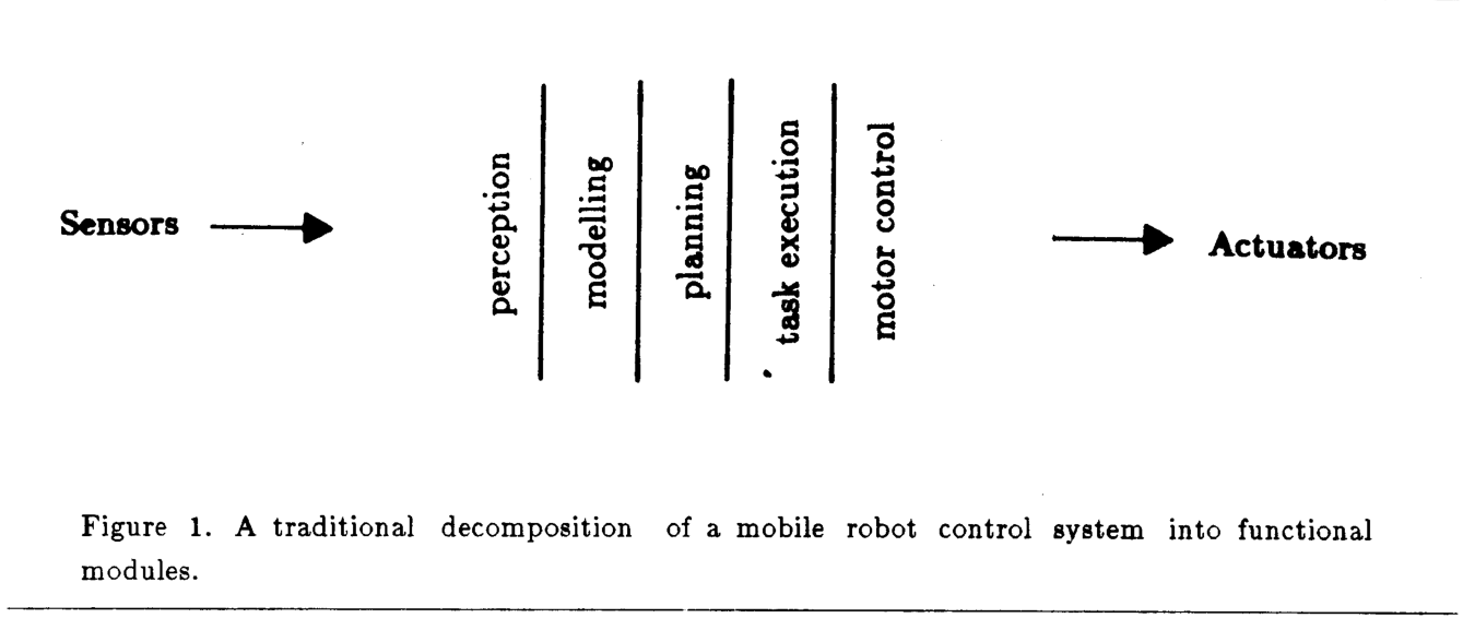
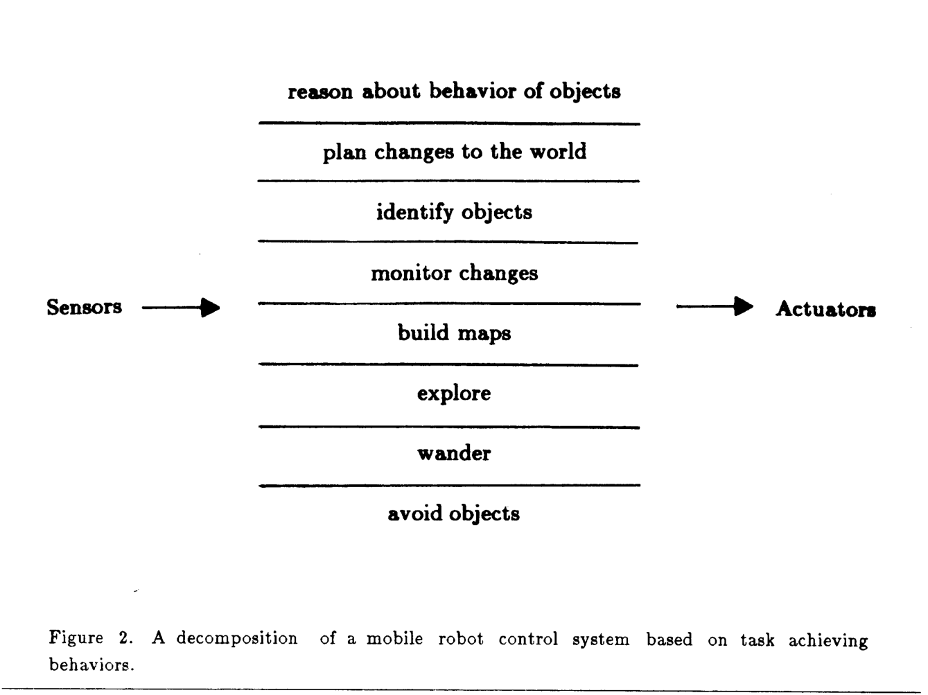
The proposed decomposition organizes a controller around externally visible behaviors. Each layer can form a working sensor-to-action system, allowing useful capability before the entire architecture is complete.
1.1 Requirements
A mobile robot must pursue concurrent goals, handle noisy or contradictory sensors, retain useful behavior after failures, and accept added computation as its capabilities grow.
1.2 Other Approaches
The review contrasts explicit exception handling, sensor fusion, and conventional multiprocessor organization with a design that tolerates independent sensing and decentralized control. Redundant sensors can remain useful without every reading entering one central world model [Flynn 85].
1.3 Starting Assumptions
The design favors simple components and interfaces, useful behavior in ordinary human environments, three-dimensional perception, relational rather than absolute maps, and continued operation when sensors fail. It treats rich behavior as partly emerging from interaction with the environment. These are design commitments, not experimentally established guarantees.
1.4 The Physical Robot
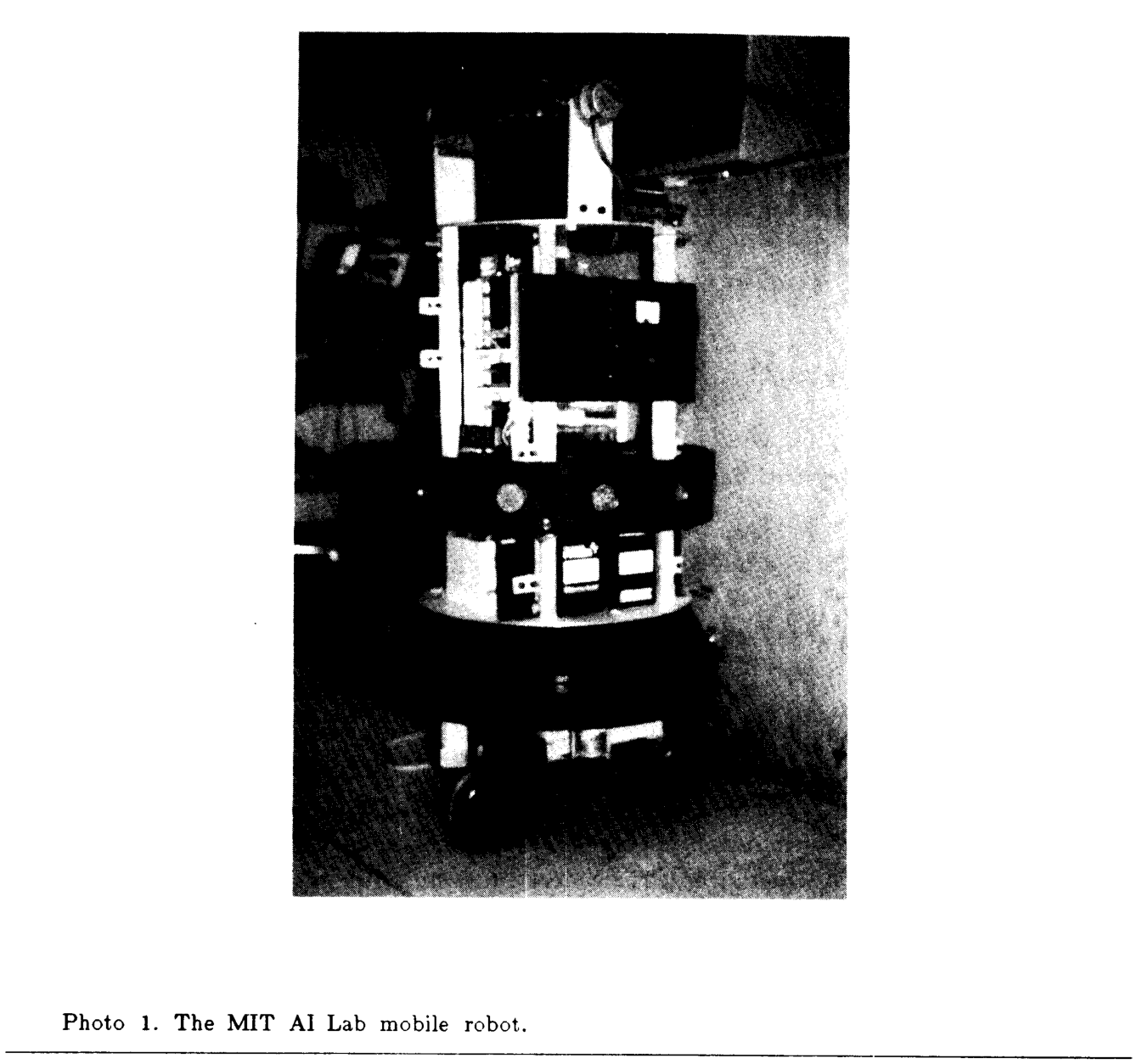
The constructed platform is about 17 inches across and 30 inches high, with three jointly steered wheels, twelve sonar sensors, and two cameras. An Intel 8031 coordinates onboard devices while radio and video links connect offboard Lisp machines. At the memo’s writing, the robot and communication links were not ready to test this controller.
2. Levels and Layers
Behavioral competence defines what a layer must accomplish; subsumption specifies how a new layer can coordinate with existing ones.
2.1 Levels of Competence
The proposed progression is: avoid contact; wander; explore visually reachable places; build maps and plan routes; detect changes; reason about identifiable objects; plan changes to the world; and reason about object behavior. Only the first two levels and part of the third are implemented here.
2.2 Layers of Control
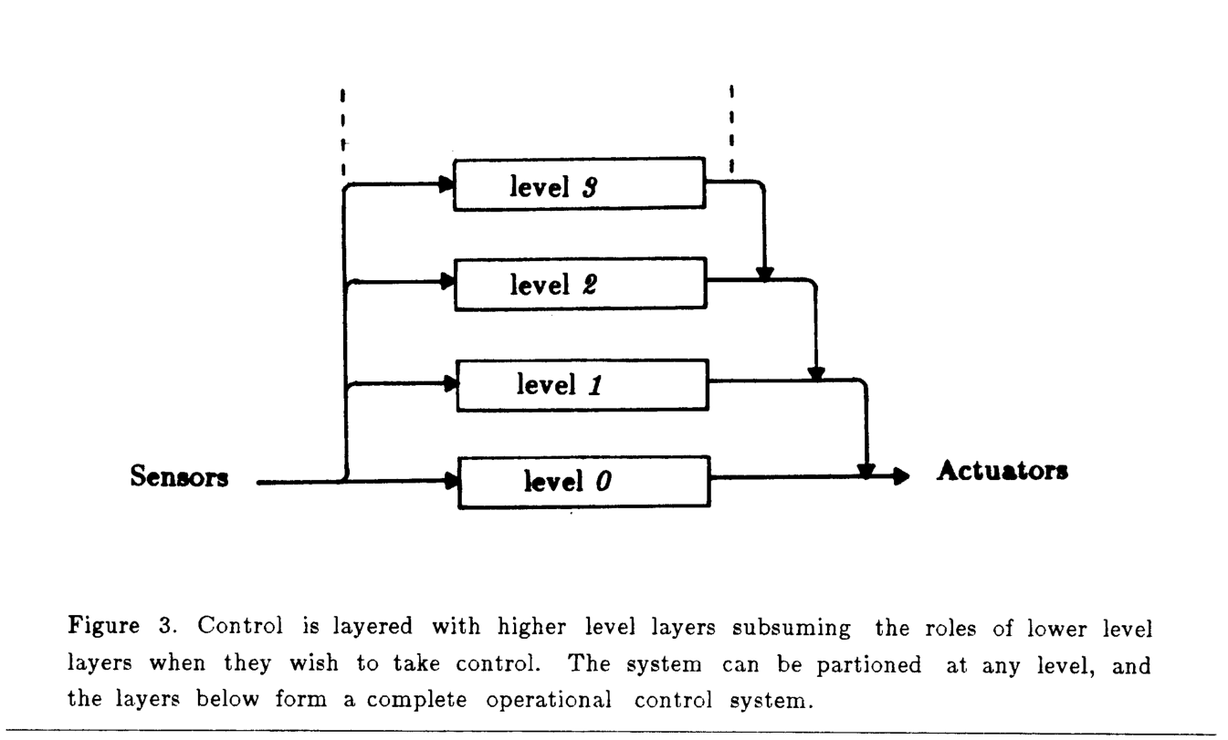
A new layer observes existing signals and temporarily injects replacements, while lower layers continue running. If a higher layer stops supplying control, lower behavior resumes. This supports incremental development and graceful loss of higher competence, although temporary suppression can also disable useful lower-level reactions.
2.3 The Structure of Layers
Layers consist of small finite-state modules with local data, asynchronous message passing, no acknowledgments, and no shared global memory. Messages may be overwritten. Control emerges from the fixed communication structure rather than a central executive.
3. A Robot Control System Specification Language
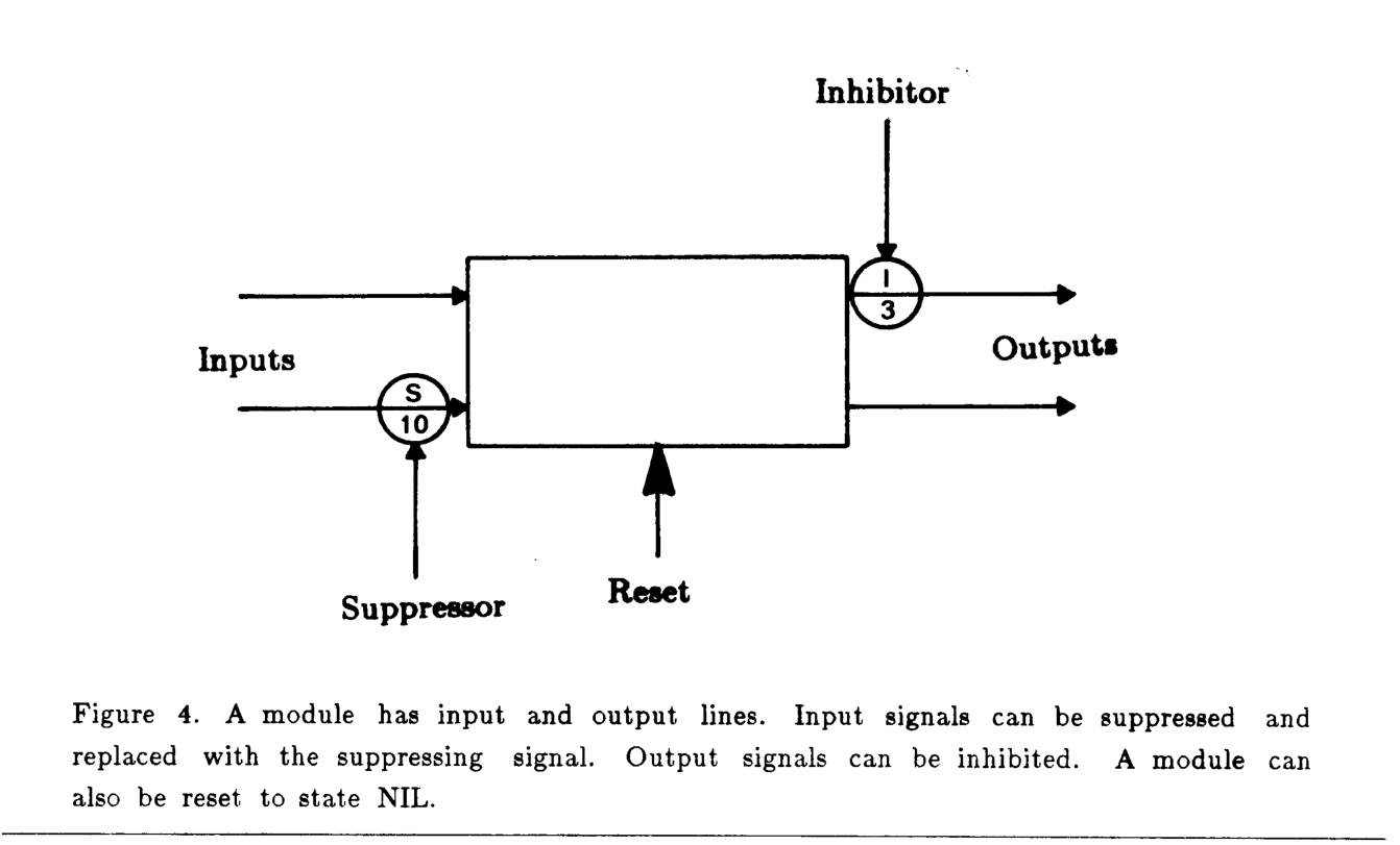
The specification language defines augmented finite-state modules and the wires connecting their inputs, outputs, resets, suppressors, and inhibitors.
3.1 Finite State Machines
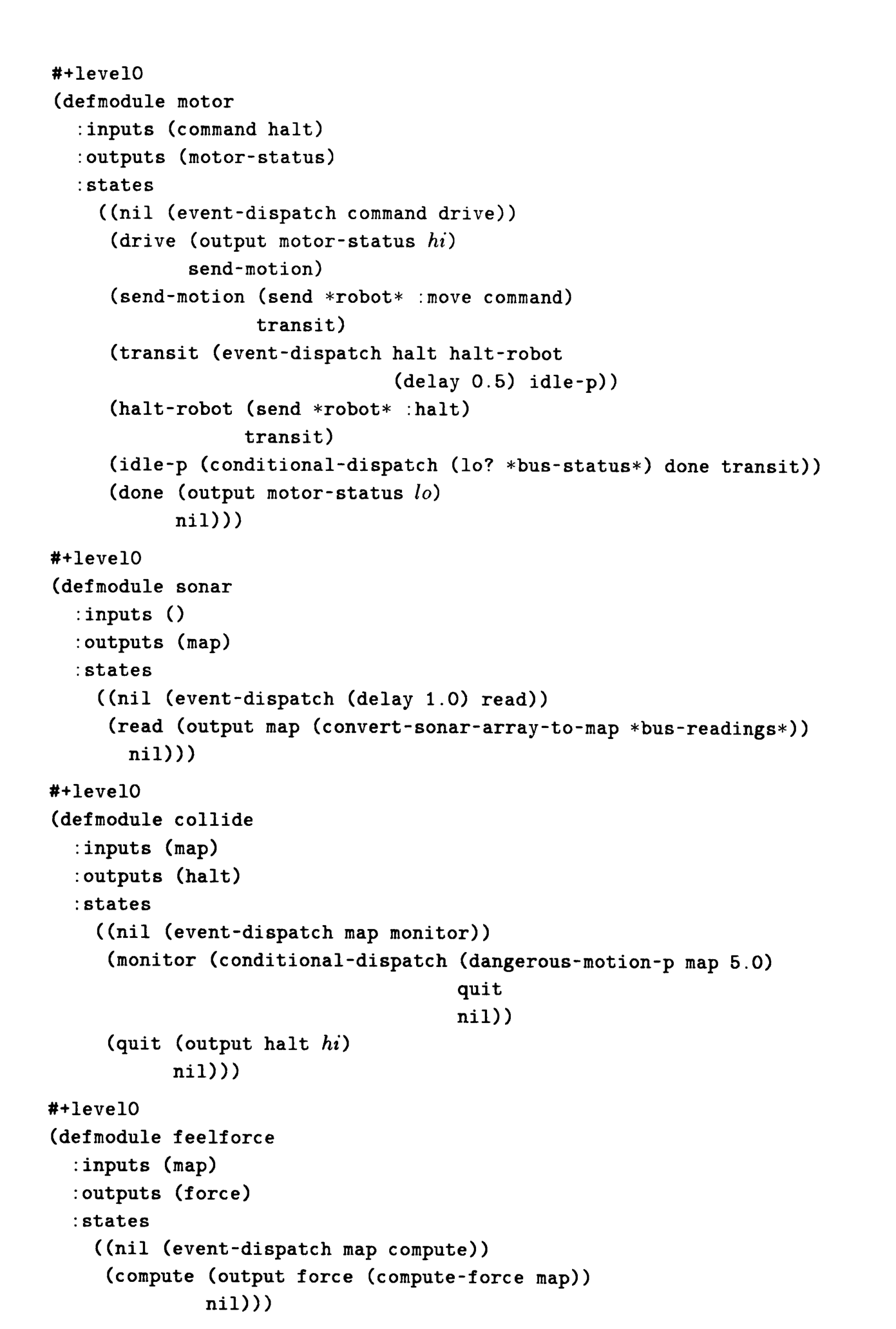
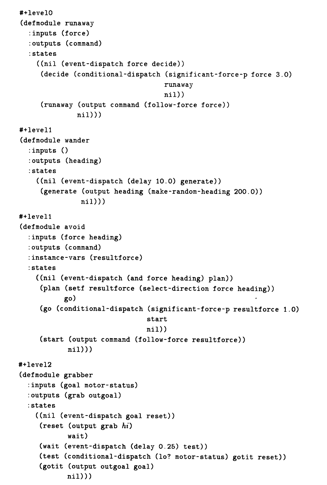
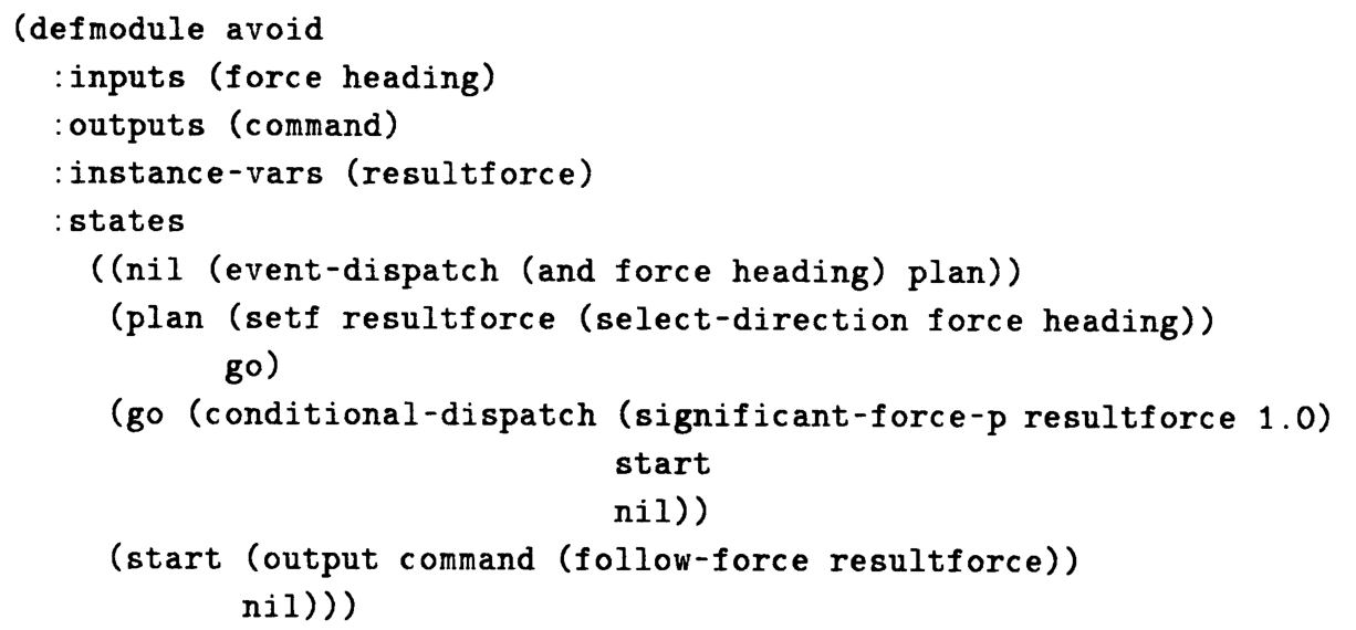
Modules start or reset in state NIL. States send output, update local variables, branch on predicates, or wait for message/timer events. Input buffers retain only the latest message. The preserved avoid listing combines a desired heading with obstacle repulsion, rejects negligible motion, and sends a motor command. It provides local avoidance, not guaranteed arrival at a global destination.
3.2 Communication
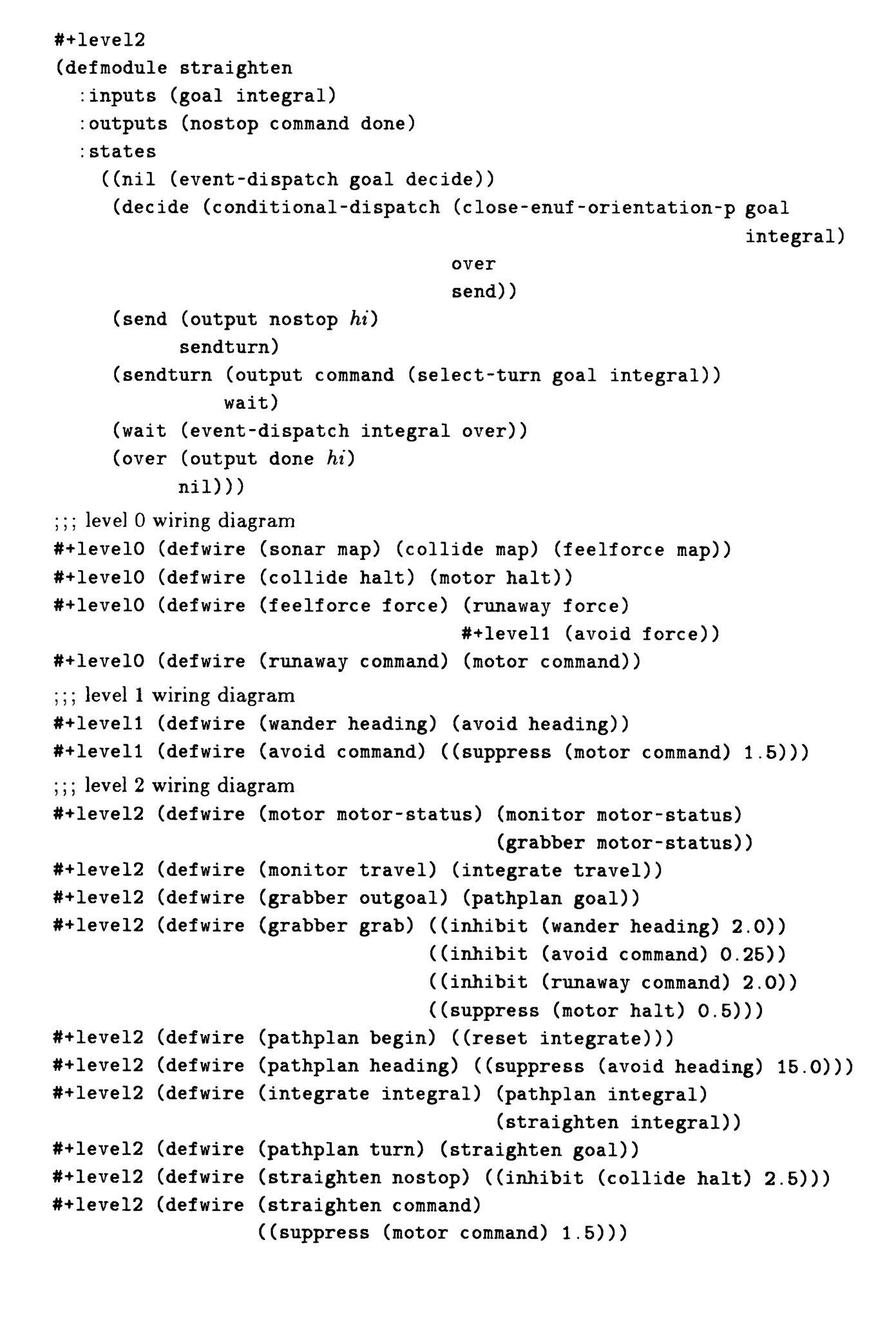
Inhibition temporarily blocks an output; suppression replaces an input with another signal. Their timeouts are part of the wiring specification. The two preserved wiring examples connect the force signal to multiple consumers and let the avoid module suppress the motor’s ordinary command input.


4. A Robot Control System Instance
The implementation has complete avoidance and wandering layers plus the nonvisual portion of goal-directed exploration. The appendix preserves all supplied modules and wiring; the underlying geometric Lisp helper functions are omitted in the original.
4.1 Zeroth Level
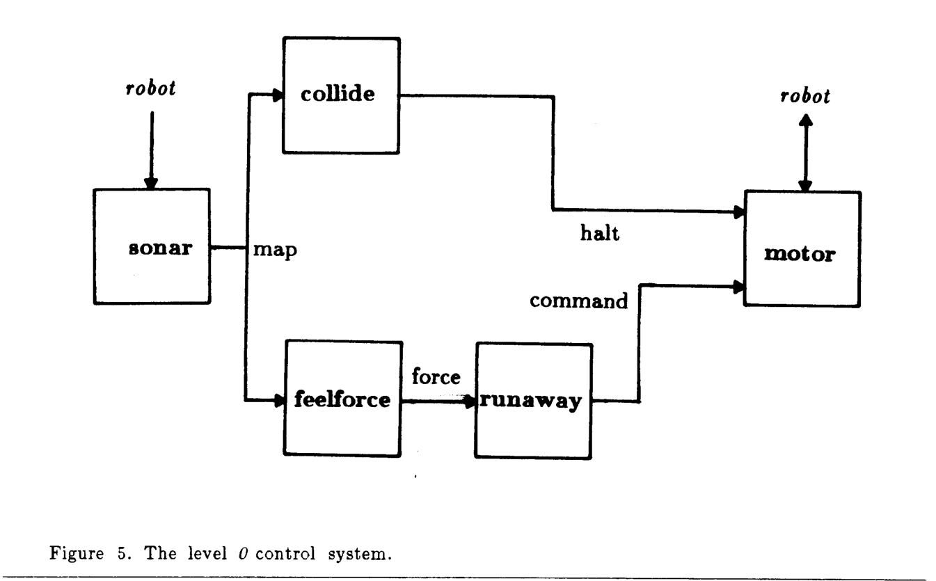
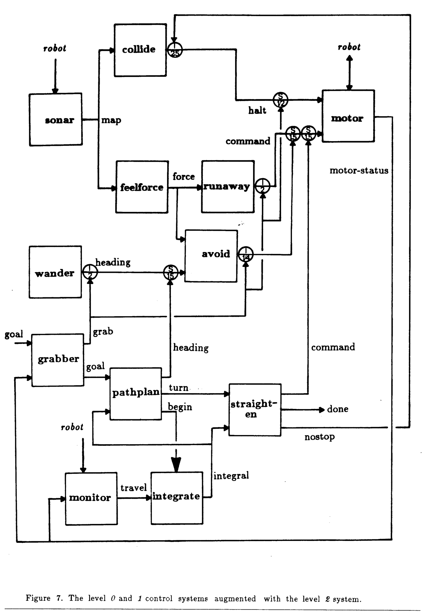
The sonar module filters readings into a local obstacle map. A collision module halts forward travel, a force module accumulates repulsion, and runaway commands escape when repulsion is large. This is a collision-avoidance heuristic: sufficiently fast moving obstacles or cramped environments can still cause collisions.
4.2 First Level
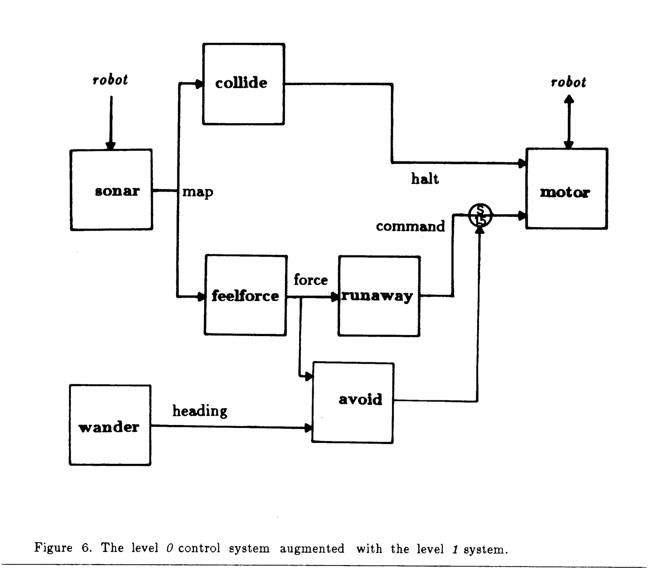
A wander module periodically chooses a heading. The avoid module bends it away from obstacles and suppresses the default runaway command. Existing sonar and collision modules remain active, so wandering is added without rewriting the lower layer.
4.3 Second Level
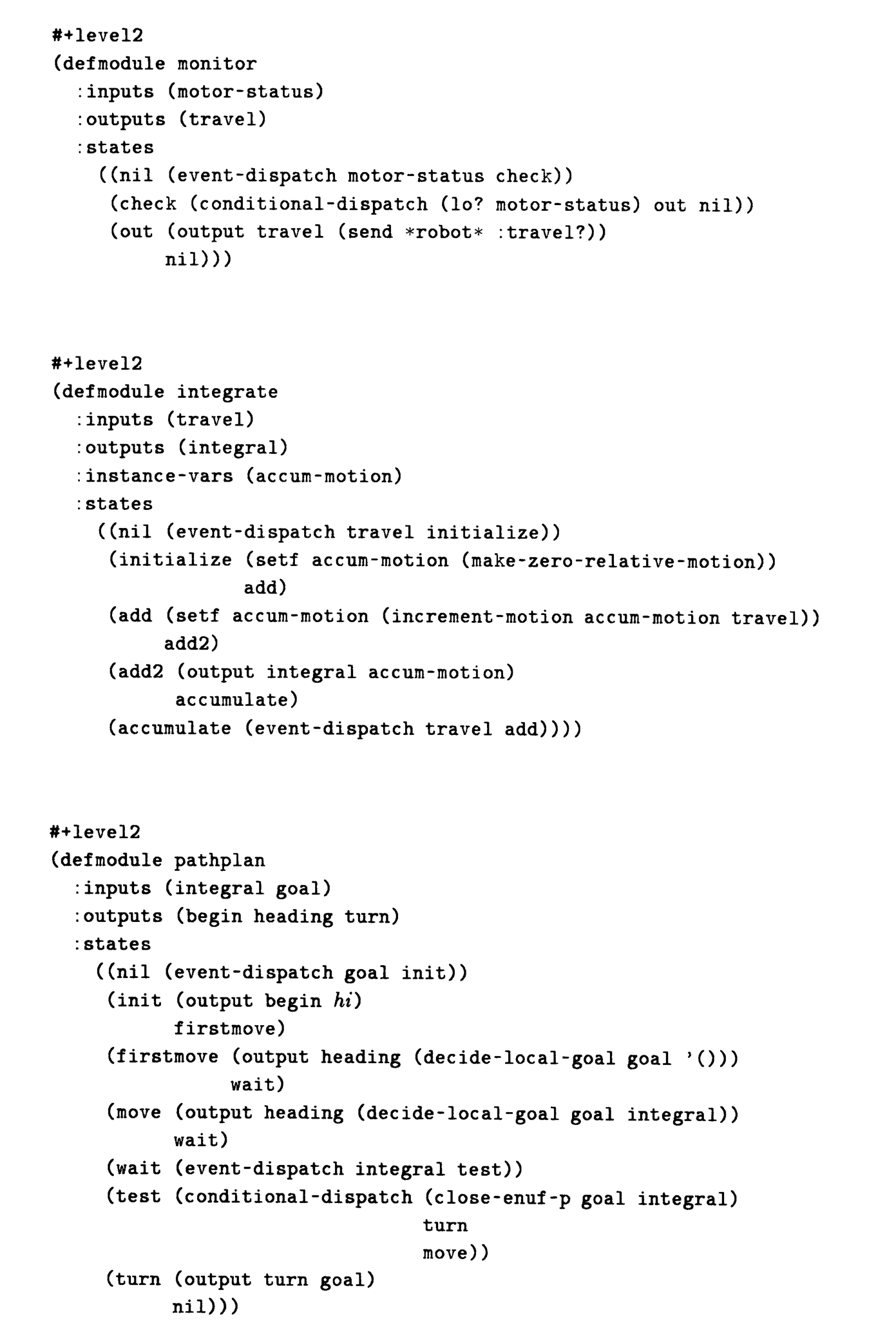
The implemented portion approaches relative goals using accumulated encoder motion, local avoidance, and a final orientation correction. A grabber briefly inhibits lower behaviors to obtain control and stable readings; the paper notes a two-second interval when approaching objects cannot be avoided. Goal progress uses dead reckoning, so slip and motion errors remain. Visual corridor selection and associated monitoring are planned, not implemented.
5. Performance
Reported tests are real-time simulations on a Lisp machine. There are no physical-robot results, aggregate success rates, or systematic robustness comparisons in this memo.
5.1 A Simulated Robot
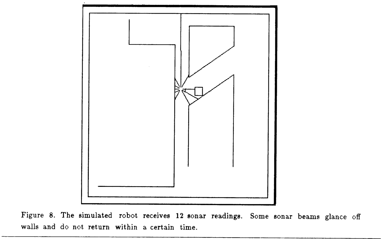
The simulator includes motion error, noisy sonar, reflections, and missing returns. It runs at the robot’s intended pace alongside the controller and graphical displays.
5.2 Zeroth and First Level
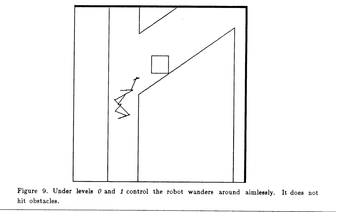
The illustrated trajectory wanders through one environment without contacting obstacles. It demonstrates operation of the two lower layers rather than exhaustive collision avoidance.
5.3 Second Level
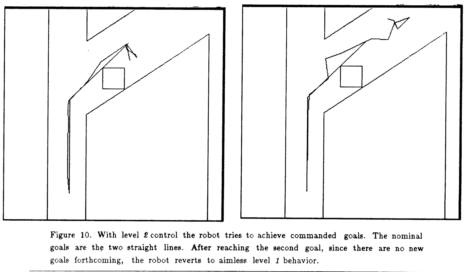
Two goal commands temporarily replace aimless wandering. With simulated uniformly distributed ±5% turn and travel errors, goals are reached only approximately; once commands end, wandering resumes.
6. Implementation Issues
Small asynchronous modules suggest a scalable processor network, but their apparently simple state machines still call geometric Lisp computations. Hardware proposals must account for those operations.
6.1 A Spatial Processor
The paper proposes a circular array of roughly sixty simple one-bit processors for each module’s spatial computations. This is a suggested implementation direction, not measured hardware performance.
6.2 Sizing The Processors
The existing simulated modules need no more than eight states. A proposed simpler gate-level implementation would use up to sixteen states and fit many controllers on a chip.
6.3 Shorter Term Approaches
A Connection Machine is proposed as an intermediate platform before custom chips, using local and routing networks for within-module and between-module communication [Hillis 85]. The anticipated low communication load has not been demonstrated at large scale.
7. Conclusion
Behavioral layers provide a path to incrementally built, decentralized robot control. The memo’s main gaps are physical validation, a complete visual exploration layer, and a clean separation between control algorithms and their implementation. Robustness is an architectural motivation supported by examples, not a formal safety result.
Acknowledgments
The work acknowledges MIT Artificial Intelligence Laboratory support, research sponsors, and colleagues who commented on drafts.
Appendix: complete control code
The four original listing pages preserve the motor, sonar, collide, feelforce, runaway, wander, avoid, grabber, monitor, integrate, pathplan, and straighten modules plus all three layers’ wiring. Lisp reader macros select which layers are loaded. Spatial helper functions are not included in the source memo.