Reading guide
This edition covers all seventeen pages, Appendices A–H, seven complete figures, six independently numbered tables, eight equations and twenty-seven references. FACT combines a low-noise training schedule with wrist-force conditioning. Its 66% mean success improves on the best force baseline’s 40.5%, but individual task results and the compliant controller matter. Original diagnostics, conditioning diagrams and every available source gallery clip accompany the paper figures.
At a glance
The paper separates failures of small corrective motion from failures to interpret contact forces, then proposes two complementary changes. Logit-Normal timestep sampling emphasizes nearly clean actions; force history, current-force normalization and contact-gated gradients add structured haptic conditioning. FACT averages 66% on five hardware tasks versus 40.5% for the strongest prior force baseline, a 25.5-point mean gain. This is not a 25-point gain on every task, and board erasing favors the unmodified visual policy.
1 Introduction
Visual action policies can lose alignment evidence precisely when contact occludes the target. Adding force alone may leave small-action prediction and temporal contact interpretation unresolved. The paper motivates two useful diagnostic categories rather than an exhaustive taxonomy or a controlled causal decomposition of every failure. Both are studied on one arm and a common impedance controller; the hardware/control stack is part of the result.

2 Related Work
The work combines classical compliant manipulation, multimodal contact learning and force-augmented generalist policies. It emphasizes training-timestep allocation and how force enters an action expert, rather than introducing a new force sensor or additional task data. Related architectures differ in temporal context, added capacity and where force conditions the model.
2.1 Contact-Rich Manipulation
Classical compliance, force control and search already address alignment uncertainty. Learned haptic, visual-force and tactile systems add richer inference but must combine sparse localized forces with dense images. FACT targets this fusion problem within flow-matching VLAs. Its low-noise intervention is not a replacement for compliant low-level control, which already solves much of sustained board contact.
2.2 Force-augmented Vision-Language-Action Models
Prior methods condition policies through force-aware routing, torque-history tokens, cross-attention or auxiliary supervision. FACT uses a shared policy backbone for reimplemented ForceVLA and TA-VLA comparisons, making their action interface and demonstrations consistent. These are the paper’s controlled reimplementations, not unchanged original systems; added parameters and force histories still differ.
3 Preliminaries
Equation1 trains a velocity field on a linear clean-action/noise interpolation. Here τ=1 is noise and τ=0 is a clean action, and inference integrates toward zero. Changing the training distribution of τ changes which denoising regions receive supervision; it does not change the inference schedule by itself. Nearby clean actions can reveal small corrections, but the equations alone do not imply that low noise uniquely corresponds to contact or prove a physical precision guarantee.
Original mathematical definitions and experimental protocol
We introduce the flow-matching policy formulation and notation used throughout the paper, with emphasis on the role of the noise level and its sampling distribution.
Original mathematical definitions and experimental protocol
Flow matching [24] trains a network to predict a time-dependent velocity field that maps samples from a noise distribution to a target distribution. In visuomotor policy learning, the target is the conditional distribution of action chunks given the current observation . Given a clean action chunk and noise , the rectified linear interpolant defines noisy actions for , with constant target velocity . The network is trained to match this target, conditioned on the observation and noise level , via the flow-matching objective

Original selectable equation
Equation 1
| (1) |
Original mathematical definitions and experimental protocol
At inference time, integrating the learned field from to maps an initial Gaussian noise action chunk to a clean action chunk . The training distribution of is set by a noise-level scheduler. Many standard choices, including the beta schedulers used in recent flow-based VLAs such as [2], concentrate probability mass on large values giving the near-clean regime fewer training samples. We focus our evaluation primarily on , with additional results on [1] and GR00T N1 [4] (Section 7).
4 Diagnosing Failures of VLA Policies in Contact-Rich Tasks
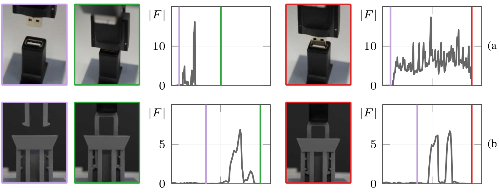
Figure2 illustrates successful seating, misalignment at the rim and an incorrectly interpreted seating event. These traces motivate distinct interventions, while both mechanisms can coexist in one rollout. Failure classification is observational: the experiments do not quantify a complete per-failure causal partition or guarantee that one intervention affects only its named category.

4.1 Precision Failures
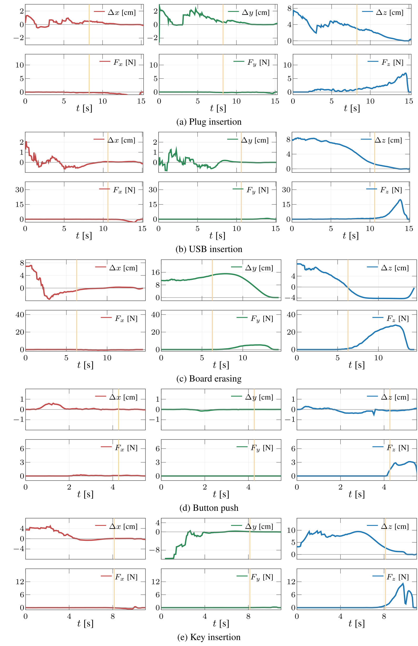
Contact phases often contain small motion deltas while the visual scene changes little. Standard Beta timestep sampling gives these nearly clean denoising states limited training mass, motivating the schedule change. The supporting action/force profiles remain in AppendixF, and held-out supervised action diagnostics in AppendixG provide a separate check. Small demonstration deltas alone do not prove the training distribution causes every alignment failure.
Original mathematical definitions and experimental protocol
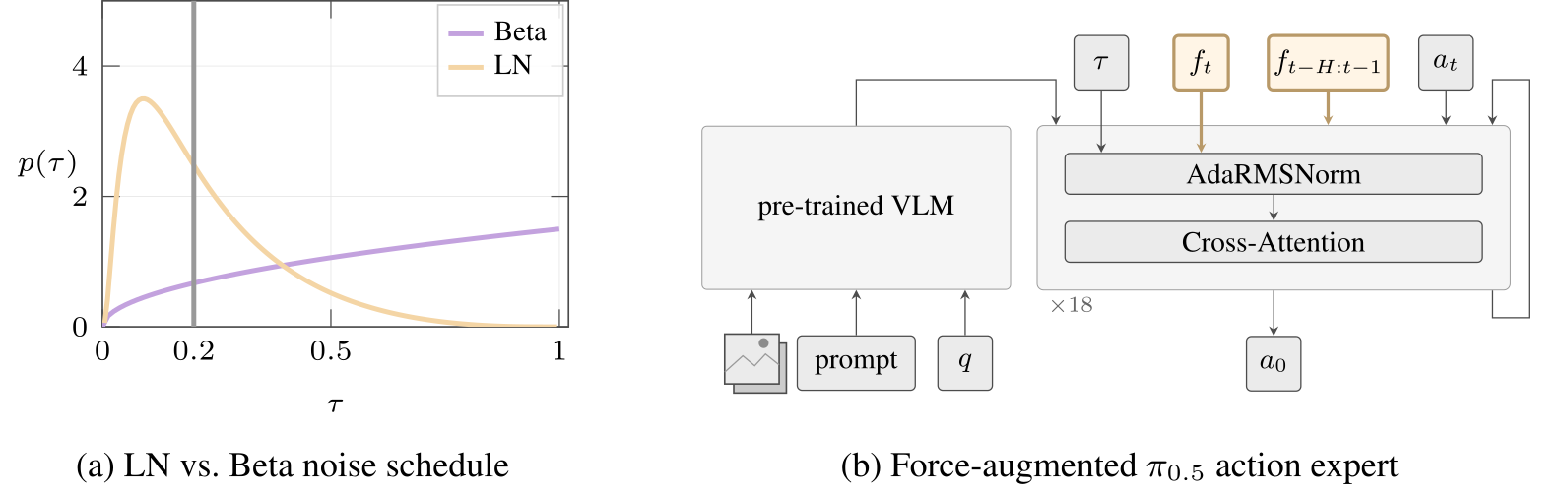
Low-noise sampling during post-training. During post-training, the Beta schedule used by [1], [2], and SmolVLA [6] allocates relatively few sampled timesteps to (Figure 3(a)). This imbalance may hinder the acquisition of fine-grained corrections needed for reliable contact-rich behavior.
4.2 Force Failures
Three force properties motivate the conditioning: near-zero free-space readings, informative temporal transitions, and a need for contact-dependent sensitivity. Current force can expose a seating peak, while history distinguishes approach, buildup and release. A gradient gate addresses which samples update force encoders; it should not be confused with removing force inputs or guaranteeing zero force influence at inference.
Original selectable panel notation
5 Addressing Failures of VLA Policies in Contact-Rich Tasks
The two interventions operate at different places. LN changes the training-time noise distribution without extra model parameters; structured force injection adds learned conditioning modules. Both reuse the same demonstrations, but FACT still requires a wrist F/T sensor and additional trainable parameters. Negligible inference overhead is asserted rather than supported by a reported end-to-end latency benchmark.
5.1 Addressing Precision Failures: Logit-Normal Noise Schedule
Equations2–3 use τ=σ(z−1.5) with unit Gaussian z. Analytically, probability below 0.2 is about 54.53%, compared with 8.94% for Beta(1.5,1), a 6.10× increase. This confirms the reported approximate 6× mass shift, not a 6× improvement in policy precision. The established Logit-Normal distribution retains support across the interval and changes post-training emphasis; its benefit remains an empirical result for the evaluated flow heads.

Original selectable equation
Equation 2
| (2) |
Original mathematical definitions and experimental protocol
is sampled via the reparameterisation:

Original selectable equation
Equation 3
| (3) |
Original mathematical definitions and experimental protocol
where is the sigmoid function. We use a location shift and scale , shifting the distribution toward lower noise levels. With this parameterization, LN allocates more sampling probability to than the Beta schedule as illustrated in Figure 3(a). This concentrates post-training on reconstructing actions from small perturbations, with the aim of improving the precise corrective actions required during contact. Critically, LN requires no changes to the model architecture, no additional training data, and no extra parameters, making it compatible with flow-matching objectives. Performance is tested on two VLA families.
5.2 Addressing Force Failures: Time-Aware Force Injection
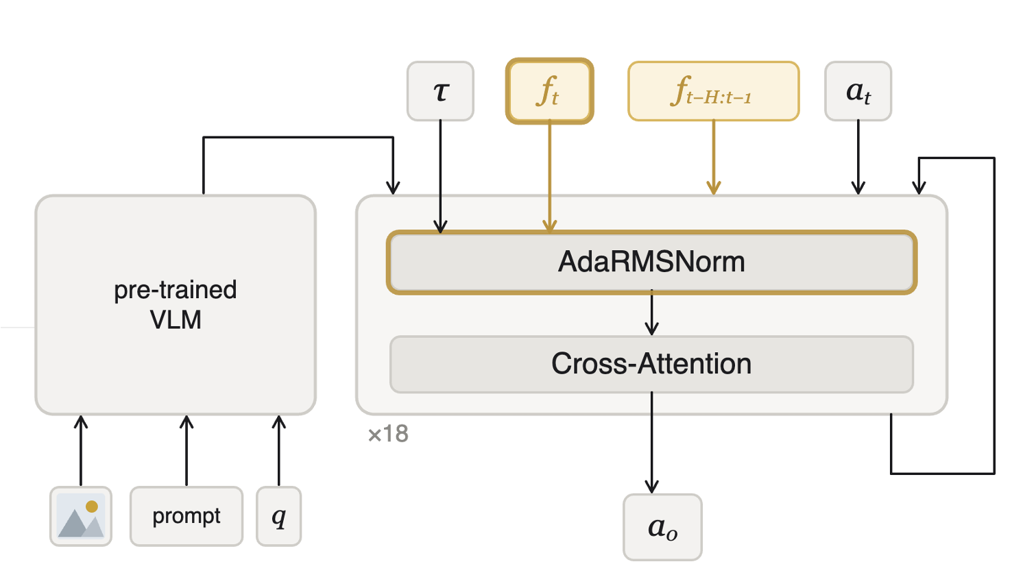
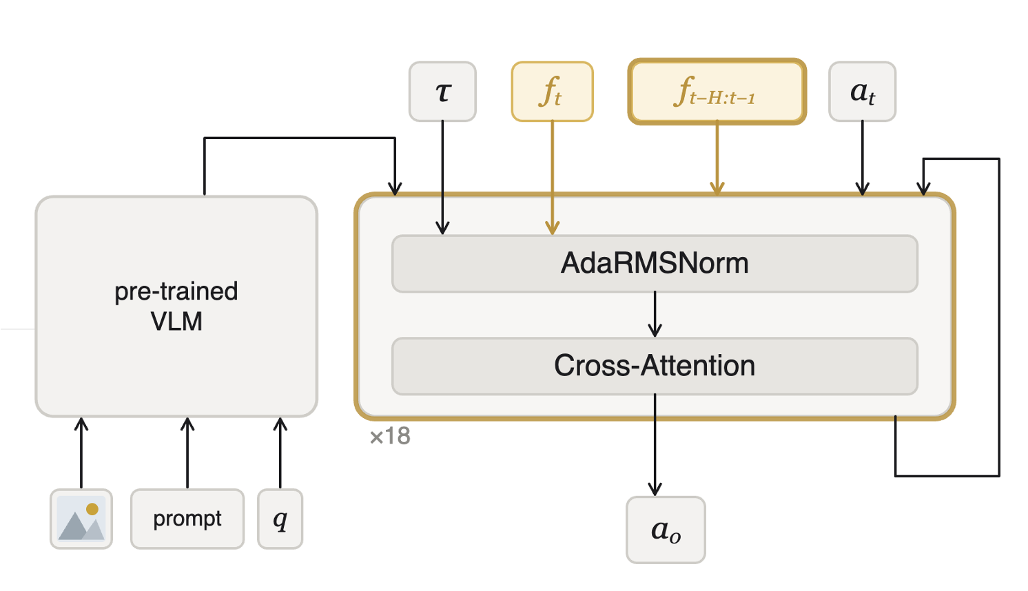
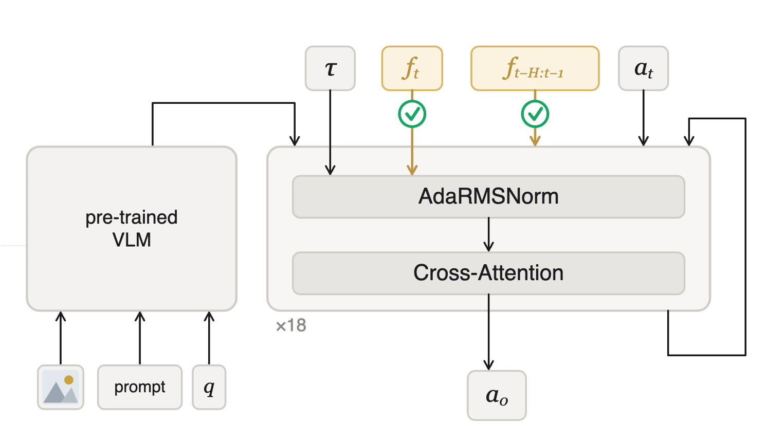
Figure3 and Equations4–5 show force-dependent normalization alongside past-force tokens. The complete equations and original model diagram remain below. The main text and AppendixE describe the exact encoder pathways somewhat differently, so the notes preserve both rather than inventing a single reconciled implementation.
Contact state.
The current 27-sample, six-axis sensor window is mean-pooled, passed through a two-layer MLP and projected to a scale correction. Equation5 adds that correction to every action-expert layer’s AdaRMS scale; the text says the correction is shared across layers. This modulates sensitivity without replacing the normal timestep conditioning. AppendixE additionally describes a causal TCN ingesting current and past windows, which is a more specific but not identical pathway description.
Original mathematical definitions and experimental protocol
Targeting sensitivity modulation, we inject the current force reading into the normalization layers of the action generation module to adapt the policy’s responsiveness to the contact state. The most recent sensor window is mean-pooled to a 6-dimensional summary , passed through a two-layer MLP, and projected to a per-layer scale modulation:

Original selectable equation
Equation 4
| (4) |

Original selectable equation
Equation 5
| (5) |
Original mathematical definitions and experimental protocol
is shared across all layers and modulates the sensitivity of every layer in a single forward pass.
Contact history.
The previous thirty policy steps provide roughly two seconds of F/T history at 15 Hz. A shared causal encoder produces tokens that are prepended to the action expert. The paper describes independent window encoding here, whereas AppendixE says windows are processed jointly. Exact temporal alignment, window summaries and the intended implementation should therefore be checked in code before replication.
Original mathematical definitions and experimental protocol
Targeting temporal structure, the preceding steps (2 s) of F/T readings are each encoded independently by a shared causal encoder [26]. The resulting tokens are prepended to the input of the action generation module, enabling the policy to reason over the trajectory of contact.
Contact gating.
The contact threshold δ=0.5 N blocks gradients through force encoders on samples classified as no-contact. This focuses training on informative events; it is a training gate, not a stated hard masking of the force pathway during deployment. Sensor bias and the precise threshold statistic affect what counts as contact. Removing this gate hurts key and button performance in the reported ablation.
Original mathematical definitions and experimental protocol
Targeting contact sparsity, a gradient gate with threshold blocks gradient through all force encoding components for steps where no contact is detected, preventing the force encoders from fitting to uninformative near-zero readings.
6 Experimental Setup
Five tasks deliberately vary whether alignment precision or a force completion cue is central. All use the same Franka arm, wrist sensor, pose-action interface and compliant controller. The evaluation randomizes positions within the training workspace and compares frozen trained checkpoints over hardware rollouts. It does not establish transfer to new sensor placements, robot embodiments or broad unseen-object distributions.
Accessible original table, all values and task labels
| Plug insertion | USB insertion | Button push | Board erasing | Key insertion | All | ||||||
| Method | SR[%] | SR[%] | SR[%] | SR[%] | SR[%] | SR[%] | |||||
| 30.0 | – | 37.5 | – | 12.5 | – | 100.0 | – | 15.0 | – | 39.0 | |
| + LN | 50.0 | 47.5 | 57.5 | 87.5 | 37.5 | 56.0 | |||||
| FACT | 57.5 | 47.5 | 75.0 | 90.0 | 60.0 | 66.0 | |||||
| ForceVLA | 32.5 | 37.5 | 12.5 | 77.5 | 42.5 | 40.5 | |||||
| TA-VLA | 30.0 | 25.0 | 20.0 | 97.5 | 15.0 | 37.5 | |||||
Tasks
Plug and USB insertion emphasize alignment under partial visual occlusion. Key insertion hides the lock and varies visually identical key lengths; button pushing uses a locking force event; board erasing tests sustained surface contact. These designed ambiguities make force informative on selected tasks, while the controller already handles much of board contact. AppendixA retains the precise task definitions and camera views.
Data Collection and Training
Each task uses 100 force-feedback teleoperated demonstrations. Target locations span 32×20 cm and home poses a 5 cm cube. Images/proprioception arrive at 15 Hz and F/T at 400 Hz. All main methods use π0.5 LoRA post-training for 20,000 steps on the same demonstrations. These controls improve comparison, although different added architectures still have different parameter counts and histories.
Original mathematical definitions and experimental protocol
All experiments are conducted on a Franka Research 3 arm equipped with a wrist-mounted Bota SensONE F/T sensor (see Appendix B for hardware details). For each task, we collect 100 teleoperated demonstrations using a Haply Inverse 3 haptic device that provides force feedback to the operator. At the start of each episode, the target position is sampled uniformly over a cm surface to encourage robustness, and the robot’s home position is sampled uniformly within a cm cube. Visual and proprioceptive observations are recorded at 15 Hz and synchronized with F/T readings recorded at 400 Hz. All methods, including baselines, are fine-tuned from the pre-trained checkpoint using LoRA for 20,000 steps on the same demonstrations.
Baselines
ForceVLA and TA-VLA are reimplemented on π0.5 to share the main backbone, then also compared on π0. Their original publications used π0, so the reimplemented rows should retain their version labels. AppendixE separates roughly 50M shared LoRA parameters from 2.2M FACT,45M ForceVLA and2.1M TA-VLA added modules.
Original mathematical definitions and experimental protocol
We compare FACT against the standard policy and two force-conditioned baselines, ForceVLA [8] and TA-VLA [9]. Although ForceVLA and TA-VLA were originally introduced using the architecture, we re-implement both methods on top of to enable a controlled comparison under a shared policy backbone. We additionally report backbone results in Table 4 to enable direct comparison with the originally proposed baseline configurations. For a detailed comparison of FACT against baseline architectures please refer to Appendix E.
Metrics and Evaluation Protocol
Each method/task condition has 40 rollouts with a 60-second timeout and poses drawn from the training distributions. Nearly 2,500 rollouts pool many methods and ablations, rather than 2,500 independent trials of the headline FACT setting. Table 1 and A.1 use directional, unadjusted Fisher tests. Their p-values compare a method to the stated reference; they do not automatically test the additional force module against the LN-only row.
Original mathematical definitions and experimental protocol
Each method is evaluated on 40 independent rollouts per task, with target and home poses sampled from the same distributions used during training. Across all conditions, this yields nearly 2,500 evaluation rollouts in total. A rollout is considered successful if the task is completed within a 60 s timeout. We report success rate (SR %) as the fraction of successful rollouts and express differences in percentage points (pp). We report one-sided Fisher’s exact tests for improvement over the baseline (see Appendix H for details).
7 Results and Discussion
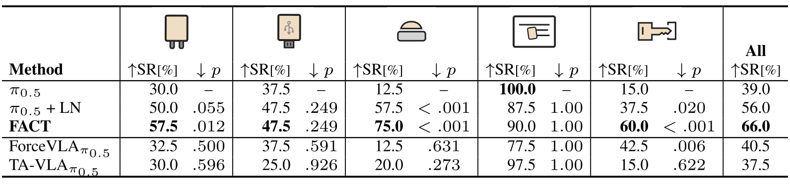
FACT’s headline mean is 66%, versus 39% for π0.5,56% for π0.5+LN,40.5% for ForceVLA and37.5% for TA-VLA. Task-level tables preserve every result and the original significance values. The strongest claim is improved mean performance with useful force-history ablations, not uniform dominance or statistically significant improvement for each task/component comparison.
Does LN improve flow-based VLAs performance on precision-critical tasks?
LN raises plug insertion30→50% and USB 37.5→47.5%, but the reported one-sided p-values are .055 and .249, above .05. It also raises button 12.5→57.5% and key 15→37.5%, while board falls 100→87.5%. Thus the low-noise intervention has a large mean benefit and mixed task effects; the two precision-task changes are not individually significant under the printed tests.
Original mathematical definitions and experimental protocol
Replacing the Beta schedule with LN improves plug insertion by 20 pp () and USB insertion by 10 pp. LN gains are also observed on force-critical tasks. Button increases by 45 pp with and key insertion 22.5 pp with . These gains require no additional data or parameters.
Does time-aware force injection improve performance on force-critical tasks?
Adding force conditioning to LN changes button 57.5→75% and key 37.5→60%, with plug 50→57.5%, USB unchanged 47.5% and board 87.5→90%. Printed p<.001 values test FACT against π0.5, not against LN. Recomputing the separate forty-versus-forty comparison gives one-sided Fisher≈.078 for button and≈.036 for key, both unadjusted. Board’s90% remains belowπ0.5’s 100% and TA-VLA’s 97.5%; its residual failures are attributed to visual coverage, not insufficient force regulation.
Original mathematical definitions and experimental protocol
Adding time-aware force injection on top of LN (FACT row in Table 1) yields 17.5 pp on button push and 22.5 pp on key insertion, confirming that force reasoning at contact is essential for tasks where visual observation is ambiguous, with for both against . On precision-critical tasks, the added force signal provides no statistically significant benefit. Board erasing stands out as an outlier among force-critical tasks, with near-perfect success rates across all methods. Sustained surface contact is largely handled by the compliant operational-space controller (Appendix C), which maintains consistent contact force without requiring explicit force reasoning from the policy. The sparse failures observed are due to visual misalignment causing the eraser to cover only part of the mark rather than failing to maintain contact with the surface.
How does each force component address the identified contact properties?
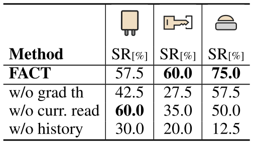
Removing history causes the largest force-critical losses: button 75→12.5% and key 60→20%. Removing current force gives 50% button and 35% key, but plug rises slightly 57.5→60%, so every component is not uniformly necessary for every task. Removing the gradient threshold gives 42.5/27.5/57.5% on plug/key/button. These ablations support usefulness in this configuration, while altered training pathways can contribute alongside information removal.
Original mathematical definitions and experimental protocol
Table 3 ablates each force component. Force history matters most, with button push dropping by 62.5 pp and key insertion by 40 pp, confirming that temporal integration is essential for force-critical tasks. The instantaneous reading plays a smaller role, except on key insertion (25 pp) where the hard-stop peak provides a completion cue that history alone cannot supply. The gradient threshold proves necessary on force-critical tasks, where contact events carry the decisive completion signal. To verify these gains reflect genuine force exploitation rather than a training regularization, we replace F/T readings with Gaussian noise during training and evaluation. Full results are in Appendix D.
Does LN recover baseline performance on precision-critical tasks?
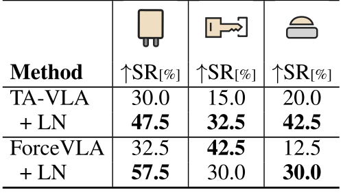
Table 2’s columns are plug, key and button, identified by the original task icons. LN improves all three TA-VLA cells and ForceVLA’s plug/button cells. ForceVLA key instead falls42.5→30%, contradicting a blanket claim of consistent gains. The schedule is an easy architectural drop-in, but that does not guarantee improvement across tasks or force encoders.
Do LN and time-aware force injection transfer to other VLA backbones like π0?
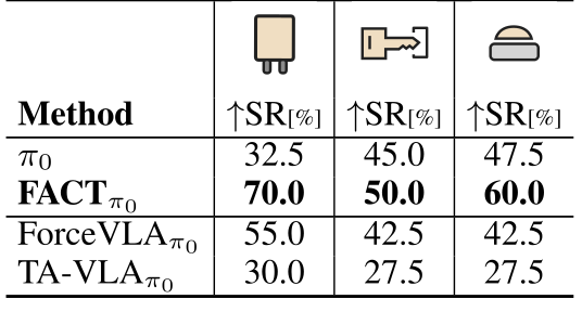
On π0, FACT reaches 70/50/60% for plug/key/button and beats the displayed baselines. Relative toπ0.5 FACT 57.5/60/75%,π0 is 12.5 points better on plug but 10/15 points lower on key/button. The prose’s ‘over10’ force-task claim therefore includes one exactly 10-point change. GR00T N1 gets plug 40→65% with LN, while key 15→12.5% with LN and 35% with FACT shows the schedule alone is not universally beneficial. This is evidence across two model families on selected tasks.
Original selectable model notation in the section title
Original mathematical definitions and experimental protocol
Table 4 evaluates FACT alongside the baselines on the backbone. FACT achieves 70.0 % on plug insertion, 50.0 % on key insertion, and 60.0 % on button push, outperforming both ForceVLA and TA-VLA. This shows that FACT transfers across backbone versions. Comparing FACT against FACT, is higher on force-critical tasks by over 10 pp, while is higher on the precision-critical task by 12.5 pp. The advantage on force-critical tasks may reflect its more explicit and pretrained timestep conditioning, which could make the force injection more effective at modulating the action expert’s sensitivity. The advantage on precision-critical tasks may come from differences in pretraining or state representation that improve fine corrections. Beyond the series, GR00T N1 plug insertion improves from 40% to 65% with LN alone. On key insertion, FACT improves success from 15% to 35%, while LN alone achieves 12.5%. These results extend the evidence to a second VLA family.
How does FACT perform on standard manipulation tasks?
Bowl stacking gives 75% FACT versus 70%π0.5 using fifteen demonstrations and 5,000 training steps, a different regime from the five-task main study. This modest single-task result does not demonstrate broad preservation of standard manipulation behavior or a universal LN benefit outside contact. The source itself calls for wider evaluation.
Original mathematical definitions and experimental protocol
On a standard bowl-stacking task, FACT achieves a 75% success rate, compared with 70% for . Because this task is simpler than the contact-rich tasks of this study, we fine-tune both methods using 15 demonstrations for 5K steps, rather than 100 demonstrations for 20K steps. These results suggest that FACT maintains performance on this standard manipulation task and offers limited additional benefit. Broader evaluation is needed to determine how LN during post-training affects tasks that do not require fine-grained corrections.
Original mathematical definitions and experimental protocol
Overall, FACT achieves 66.0 % success, outperforming ForceVLA (40.5 %) and TA-VLA (37.5 %) with consistent gains on both precision- and force-critical tasks, suggesting that addressing each failure mode independently leads to more consistent gains across contact-rich tasks.
8 Conclusion
The combination improves mean performance in the tested contact-rich setup, and the ablations support separating training-noise emphasis from structured force context. Reported per-task exceptions, controller assistance and statistical references narrow the conclusion. The result motivates testing these interfaces on more embodiments and matched force architectures rather than assuming contact failure has a single general fix.
Original mathematical definitions and experimental protocol
We present FACT, a method that addresses two distinct failure modes of flow-based VLAs on contact-rich tasks. We identify precision failures and force failures, and propose targeted solutions for each. The LN noise schedule reallocates training samples to the low-noise denoising regime, yielding consistent gains on precision-critical tasks without additional parameters or data. The time-aware force injection mechanism captures the sparsity and temporal structure of force signals, yielding large gains on force-critical tasks where visual feedback is insufficient. The two components are complementary. LN improves the prediction of small corrective actions, while structured force conditioning provides complementary gains on tasks requiring force feedback. Results on the series and GR00T N1 demonstrate transfer across two VLA families, suggesting they address general limitations of flow-based VLAs.
Limitations.
One robot, one fixed wrist F/T sensor and a small task set limit generalization. The LN intervention is evaluated for flow-matching heads; direct application to autoregressive or different diffusion samplers is not established. AdaRMS conditioning needs adaptation for other action architectures. Unseen objects, different sensor placements, richer standard tasks and controlled capacity/history comparisons remain open.
Acknowledgements
The acknowledgements identify Agile Robotics support, individual fellowships and contributions to discussion, hardware/data collection and camera footage. These credits remain represented separately from the technical claims and evidence.
Appendix A Task Descriptions
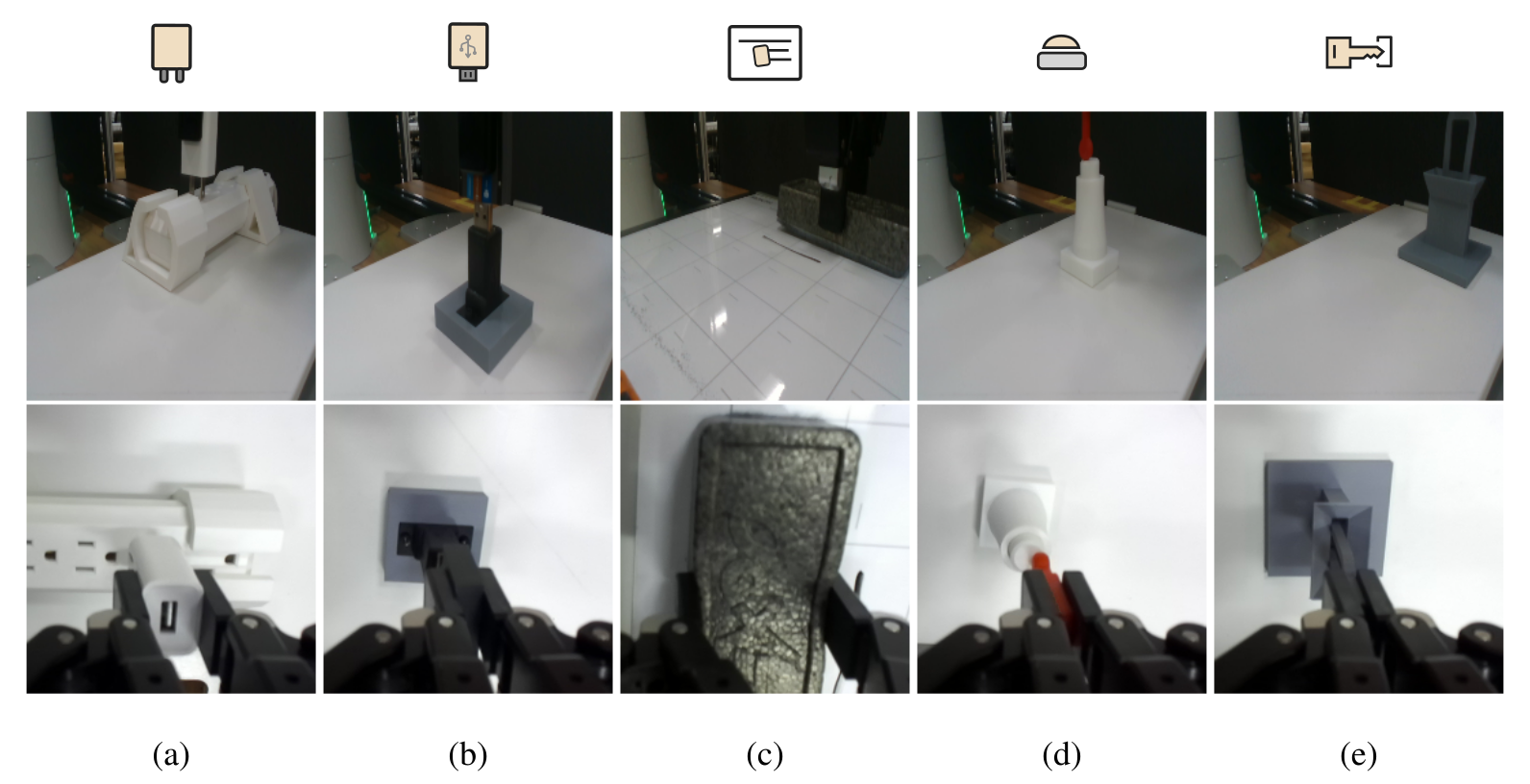
The five task descriptions below explain why vision and force provide different cues. Figure A.1 retains all ten external/wrist images, task icons and labels. The tasks are deliberately mounted and repositioned rather than a general unstructured household test.
Plug insertion
The two-pin plug obscures the socket holes on approach and needs sustained force to overcome its friction fit. Both alignment and full seating matter; the source force trace distinguishes contact, entry and the final rise.
USB insertion
A USB-A body hides its port from the wrist camera during insertion. The policy must align precisely and continue through the friction fit. The experiment uses the NIST assembly-board connector mounted on a repositionable base.
Board eraser
Erasing requires adequate continuous pressure while covering the marked region. The compliant controller makes pressure regulation comparatively easy here. A policy can still fail by erasing the wrong area, so success does not isolate haptic reasoning.
Button push
The button locks after the required force event. Demonstrations make simply pressing with maximum force unsuitable, and vision is unreliable for detecting the lock. Force history therefore supplies a completion cue rather than merely a stronger push command.
Key insertion
Visually identical keys of different lengths deliberately obscure the correct seating depth. Success requires neither stopping early nor continuing past the hard stop. An open-back lock appears in explanatory images for clarity, while execution keeps the lock occluded.
Appendix B Hardware Setup
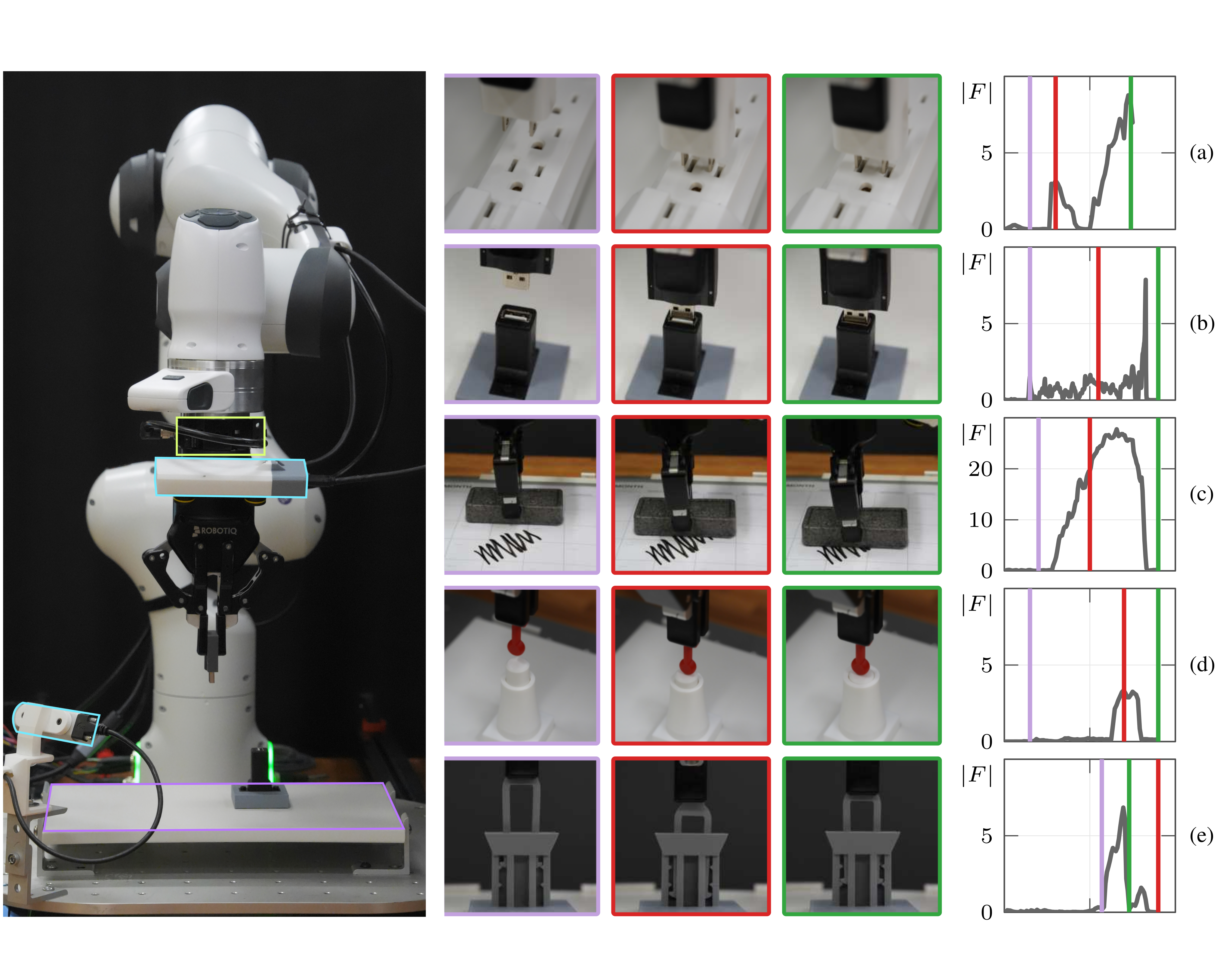
A Bota SensONE six-axis sensor sits between the Franka wrist and Robotiq gripper. D435 external and ZED Mini wrist cameras run at 15 Hz; F/T runs at 400 Hz through a one-euro filter, giving 27 readings per policy window. Cartesian impedance executes at 1 kHz. Magnetic 3D-printed mounts hold objects on a ferromagnetic board across repositioned trials. Figure A.2 preserves the full setup plus all five multi-stage image/force rows.
Original mathematical definitions and experimental protocol
All experiments are conducted on a single Franka Research 3 arm equipped with a wrist-mounted Bota SensONE 6-axis force/torque (F/T) sensor. The full setup is illustrated in Figure A.2. The robot is controlled via Cartesian impedance control at 1 kHz. Futher details on the controller design are provided in Appendix C. Visual observations are provided by an external Realsense D435 camera and a wrist-mounted ZED Mini camera, both operating at 15 Hz. F/T data is acquired at 400 Hz and pre-processed with a one-euro filter [27]. Each control step therefore receives a window of raw sensor readings ().
Original mathematical definitions and experimental protocol
All task objects were mounted on 3D-printed bases with embedded magnets, secured to a ferromagnetic board to prevent displacement during execution while allowing repositioning between trials. The plug insertion target was a commercial power strip extension held in a 3D-printed magnetic mount. The USB insertion used the connector from the NIST Robotic Assembly Board in a 3D-printed magnetic mount. The button push and key lock mechanisms were fully 3D-printed. For board erasing, the board was fixed and the drawn mark to be erased was varied between trials. A full bill of materials and 3D-printable STL files will be released alongside the code. Across all tasks, object positions were sampled uniformly within a cm workspace.
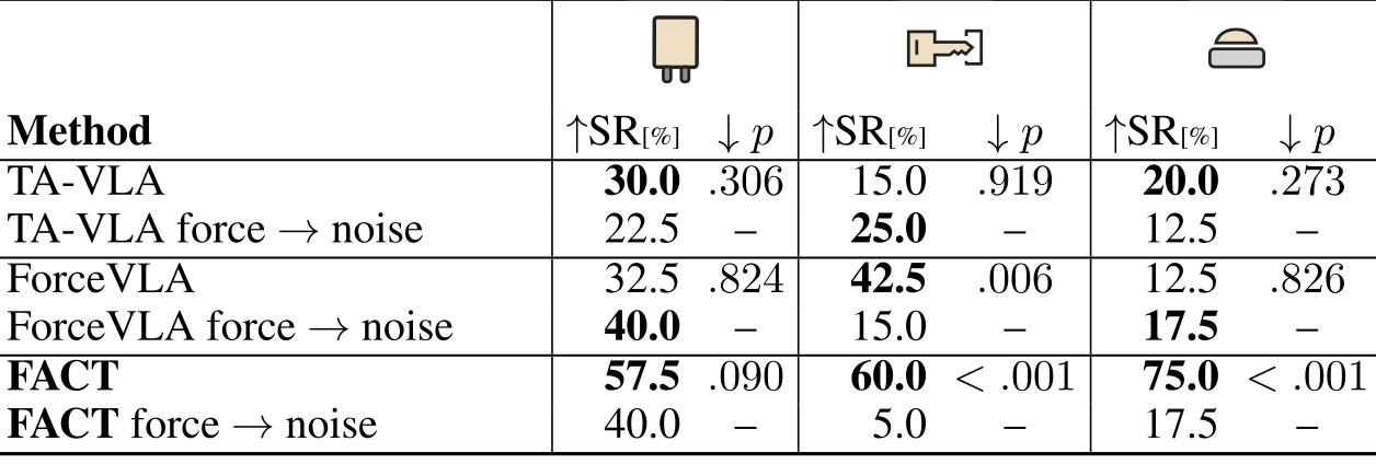
Accessible original table, all values and task labels
| Plug insertion | Key insertion | Button push | ||||
| Method | SR[%] | SR[%] | SR[%] | |||
| TA-VLA | 30.0 | 15.0 | 20.0 | |||
| TA-VLA force noise | 22.5 | – | 25.0 | – | 12.5 | – |
| ForceVLA | 32.5 | 42.5 | 12.5 | |||
| ForceVLA force noise | 40.0 | – | 15.0 | – | 17.5 | – |
| FACT | 57.5 | 60.0 | 75.0 | |||
| FACT force noise | 40.0 | – | 5.0 | – | 17.5 | – |
Appendix C Controller Design
The system separates 15 Hz policy decisions from a 1 kHz compliant torque controller. It generates a smooth desired trajectory, computes an impedance acceleration and maps it through operational-space dynamics. This common controller contributes physical compliance to every method; success cannot be attributed to learned force conditioning alone.
Original mathematical definitions and experimental protocol
We use a two-rate control architecture that decouples 15 Hz policy updates from a 1 kHz joint-torque control loop, enabling compliant behavior during contact via operational-space control [14, 18]. Let denote end-effector position and its orientation. The policy outputs Cartesian end-effector displacement commands and angle displacements . The controller framework comprises three stages of trajectory generation, impedance control, and operational-space torque computation.
Trajectory generation.
The policy outputs Cartesian translation and angular displacements. A trajectory generator converts them into desired poses with interpolated position, velocity and acceleration at 1 kHz. This bridges policy and controller rates without implying that the learned policy reacts at 1 kHz.
Original mathematical definitions and experimental protocol
At each policy step, the trajectory generator computes a desired end-effector pose from the current pose and the commanded displacements and . It then interpolates a smooth trajectory of position, velocity, and acceleration at 1 kHz, bridging the gap between the low-bandwidth policy and the high-bandwidth controller.
Impedance control.
Equation 6 adds manually tuned stiffness and damping feedback to desired acceleration. Passive compliance helps sliding and uncertain contact. The source does not provide a global safety or contact-stability certificate for the learned closed loop.

Original selectable equation
Equation 6
| (6) |
Original mathematical definitions and experimental protocol
where and are manually tuned stiffness and damping gains. Compliance during contact makes the robot safer and allows it to slide along surfaces under uncertainty, which is beneficial for contact-rich tasks.
Operational-space torque computation.
Equations 7–8 map acceleration through Λ(q) to task-space force, then through the transposed Jacobian to joint torque. The text first calls Λ operational-space inertia and later joint-space inertia; the displayed use is the task-space formulation. This notation inconsistency is preserved without inferring that the implemented controller uses the wrong dynamics.
Original mathematical definitions and experimental protocol
Using the known kinematic and dynamic model of the robot, we compute joint torques from Cartesian-space accelerations via the dynamically consistent operational-space formulation [14]. The task-space acceleration is first mapped to a task-space force via the operational-space inertia matrix ,

Original selectable equation
Equation 7
| (7) |

Original selectable equation
Equation 8
| (8) |
Original mathematical definitions and experimental protocol
where is the Jacobian at joint configuration and is the joint-space inertia matrix.
Appendix D Noise Ablation
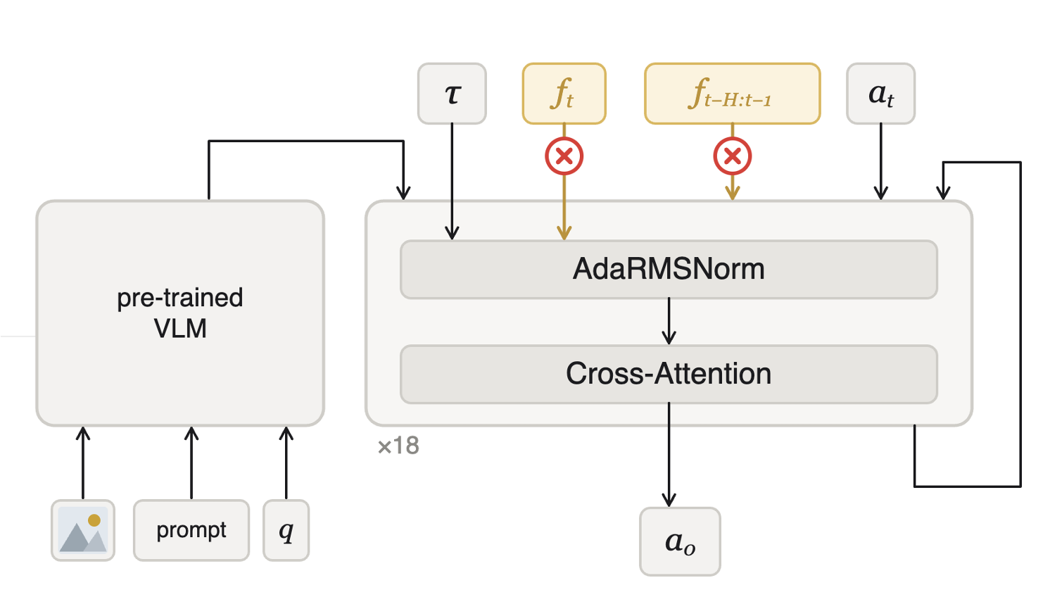
Each noise-substitution policy is retrained and evaluated using independent zero-mean unit Gaussian values instead of measured F/T, preserving input dimensionality while removing task-specific haptics. FACT key 60→5% and button 75→17.5% strongly favor real force; plug 57.5→40% has p=.090. ForceVLA’s key 42.5→15% is significant; no TA-VLA difference reaches the printed threshold. A non-significant result is not proof of no force use, and retraining noise substitution is not a pure test-time causal intervention.
Original mathematical definitions and experimental protocol
Replacing F/T with Gaussian noise yields no statistically significant change on plug insertion. In contrast, FACT shows significant drops on key insertion and button push (), supporting its use of force information on these tasks. ForceVLA also benefits from real F/T on key insertion, where success drops from 42.5 % to 15.0 % under noise replacement. TA-VLA shows no statistically significant differences on key insertion or button push.
Appendix E Baseline Architecture Comparison
Table A.2 retains force encoders, injection points, histories, gradient gating and added parameter counts for all methods. The comparison controls the backbone/LoRA/action/controller, while capacity and temporal inputs differ substantially. The full added 50M shared LoRA budget should not be excluded when interpreting the small 2.2M FACT conditioning module.

Accessible original table, all values and task labels
Original mathematical definitions and experimental protocol
Table A.2 summarises the architectural differences between FACT and the two re-implemented baselines. All three are built on the same backbone with identical LoRA adapters ( M trainable parameters), output delta end-effector pose actions, and are executed by the controller of Appendix C. “Added parameters” counts only the modules introduced on top of this shared base.
Where the added parameters live.
FACT’s ≈2.2M additions split between a ≈0.2M four-block dilated causal TCN and ≈2.1M conditioning head; rounded parts need not sum exactly. ForceVLA adds ≈45M mainly in its four-expert routing block, versus ≈2.1M TA-VLA. The main text mean-pooling/MLP current-force path and this appendix’s TCN/current-window description are not identical and need implementation-level clarification.
Original mathematical definitions and experimental protocol
The three methods sit at very different points on the capacity-vs.-temporal-context spectrum. TA-VLA adds a 2-layer force MLP (, M) that encodes a history of force readings into a single token appended to the action-expert prefix. ForceVLA projects the current F/T reading through a single linear layer (, K) and routes it through a 4-expert LIMoE block placed between the VLM prefix and the action expert, with almost all of its M added parameters sitting in the LIMoE experts and gate rather than in the force encoder itself. FACT splits its M budget between a shared causal TCN ( M, 4 dilated blocks, hidden width 64) that ingests both the current 27-sample window and the past windows, and an AdaRMS conditioning head ( M, two MLP layers and a zero-initialized -projection) that modulates the action-expert RMSNorm scales at every layer.
Force signal.
All policies use the same measured six-axis wrist signal but different histories: ForceVLA a current synchronized reading, TA-VLA roughly two seconds compressed into one token, and FACT thirty past windows plus the current window. This controls sensor hardware but does not match temporal access or encoder capacity. The appendix describes joint causal processing of windows, unlike the independent-encoding wording in the main section.
Original mathematical definitions and experimental protocol
All three methods consume the same 6-D wrist F/T readings from the Bota SensONE, but differ in temporal context. ForceVLA uses only the single reading synchronized with the current vision and proprioception step. TA-VLA keeps a history of such readings, encoding s of past F/T into a single token. FACT augments the current 27-sample window with past window summaries ( s of history at 15 Hz), which the shared causal TCN processes jointly.
Action space.
Every method predicts delta end-effector pose commands and uses the same low-level controller. This removes action-interface differences from these comparisons, while leaving visual/force representation and training-schedule differences as intended changes.
Appendix F Per-Task End-Effector Deltas and Force Profiles
Figure A.3 retains all thirty position-delta/force plots across five tasks, with units, axes and contact-onset lines. These are sample profiles illustrating shrinking motions and changing forces, not pooled distributions, error estimates or proof that all contact phases have the same dynamics.
Appendix G Action Prediction Accuracy
Twenty held-out plug demonstrations probe the learned field and reconstruct actions from matched noisy starts. For motions below 5 mm, LN lowers low-noise flow error 8–13% and Cartesian reconstruction error 5–13%; for 12–20 mm actions reconstruction improves 2–7%. These supervised diagnostics support a precision explanation, while they are not separate hardware success trials or an exhaustive causal attribution of the rollout gains.
Original mathematical definitions and experimental protocol
We probe the learned flow field on 20 plug demonstrations reserved for evaluation. Given demonstrated actions , construct with at . We compare policies adapted with LN and Beta schedules using supervised flow error . For mm actions, LN yields 8 to 13% lower error throughout the region of low noise levels. Starting from the same noisy actions, integrate the remaining Euler trajectory and measure Cartesian reconstruction error . LN reduces reconstruction error at every tested start time by 5 to 13% for mm actions and by 2 to 7% for 12 to 20 mm actions. These diagnostics support improved prediction of small corrective actions.
Appendix H Statistical Tests
Tables 1 and A.1 use forty-versus-forty success/failure contingency tables with a directional Fisher alternative and α=.05. Tests are unadjusted individual comparisons. Table 1’s reference is π0.5;A.1 compares measured force to noise within a method. Multiple comparisons, training-seed uncertainty and shared-model/task dependence limit broad significance claims beyond those exact comparisons.
Original mathematical definitions and experimental protocol
For Tables 1 and A.1, we form a contingency table of successful and failed rollouts, using 40 rollouts per method on each task. We use directional Fisher exact tests. In Table 1, the alternative is that the evaluated method has a higher success probability than . In Table A.1, the alternative is that measured F/T yields higher success than noise substitution within each method. We report unadjusted values for individual comparisons and use a significance threshold of .
Original diagnostic and robot demonstration media
The official media include an overview, three plain and three force-trace diagnostic animations, four conditioning diagrams and the task/policy/outcome gallery. Both camera views are retained with the source task, method and success/failure labels. The paired views depict the same rollout, not two independent trials. Preview posters are extracted from unchanged source clips; the gallery is qualitative evidence and does not add to the paper’s evaluation denominators.