Overview
Project repository. This edition follows the complete twenty-nine-page, 16 October 2026 v3, including all twelve figures, thirteen PDF tables and the teleoperation action display. The benchmark-comparison table missing from the arXiv HTML is restored from PDF page 16; displayed table numbering follows the PDF.
At a glance
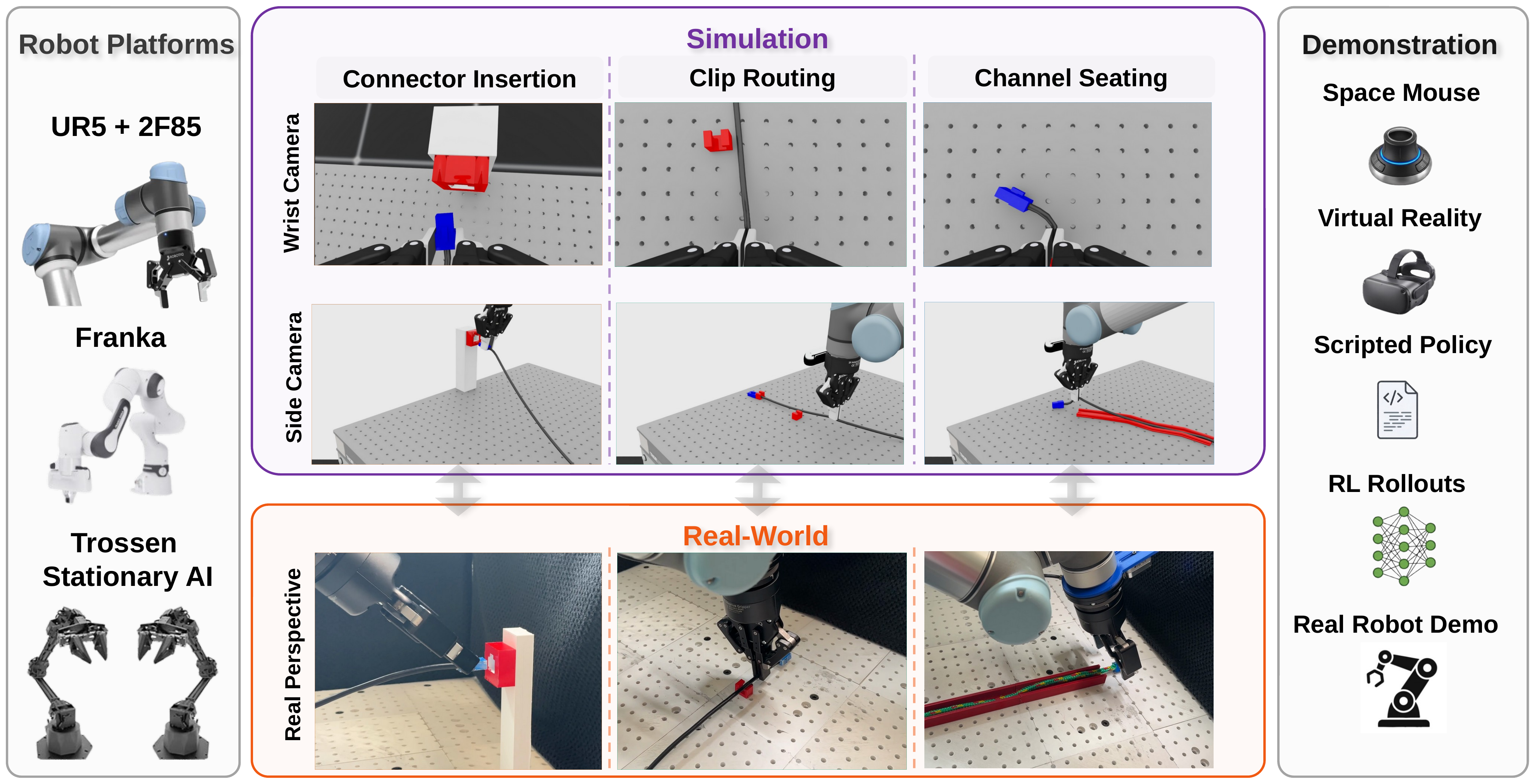
WireCraft benchmarks fixture-constrained wire manipulation: inserting a connector, routing a cable through clips and seating its body in a channel. It combines configurable assets, articulated and FEM wire models, common data interfaces and physical UR5 validation. Privileged state policies solve selected simulated settings above 82%; image-based baselines are substantially weaker. Adding simulation data to real demonstrations improves the best observed hardware result by 15–65 percentage points across tasks, but this is data-assisted adaptation rather than demonstrated zero-shot transfer.
1 Introduction
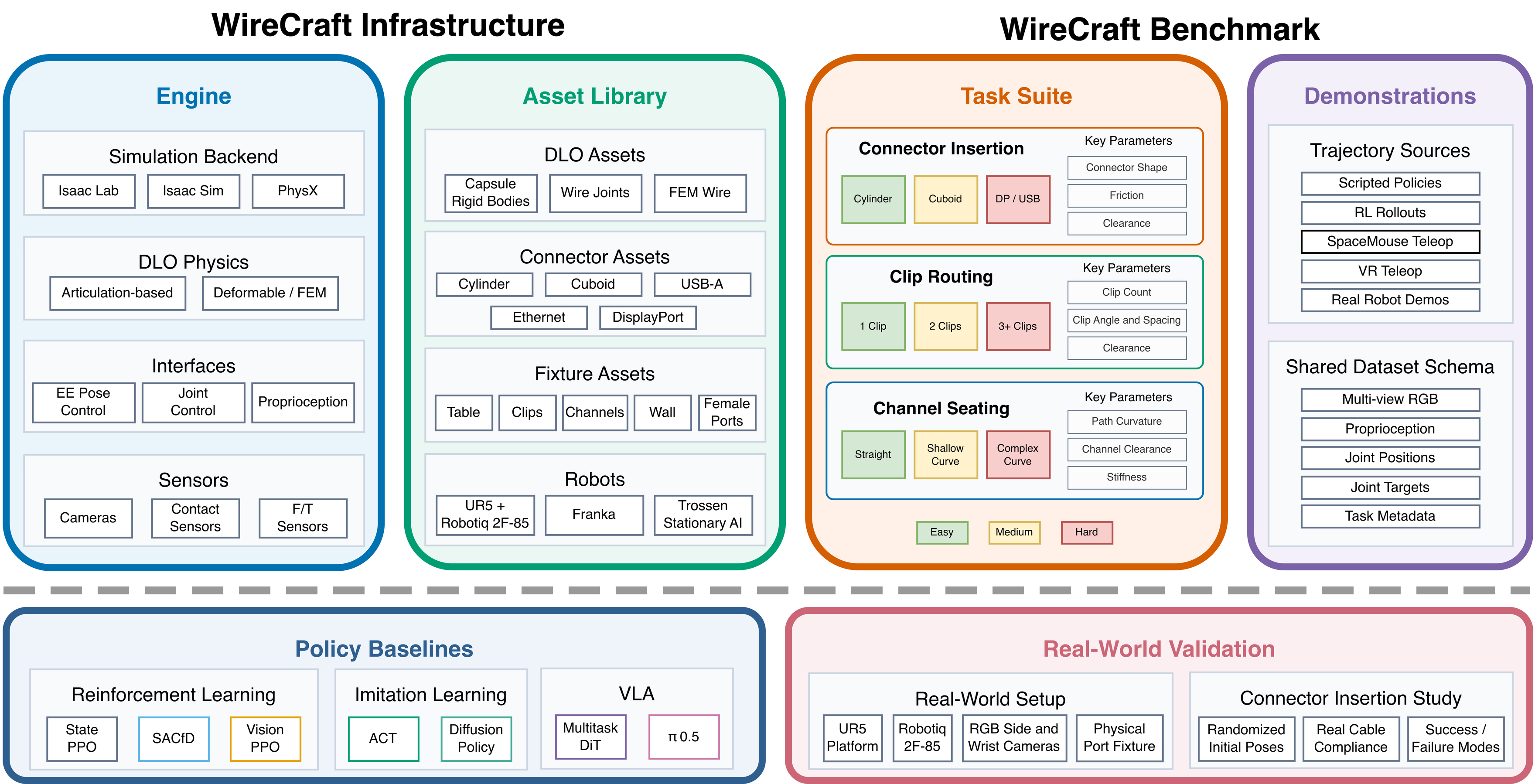
Industrial wire handling requires both precise connector poses and control of a deforming body that interacts with fixtures, the table and itself. Existing general manipulation suites, deformable-object simulators and physical task boards cover different parts of this problem. WireCraft joins three industrial task families, printable fixtures, compatible demonstrations and shared evaluation criteria.
The contribution is benchmark infrastructure and a reference study, not a new universally reliable manipulation policy. Configurable difficulty and three supported simulated arms extend the available task space beyond the narrower settings actually evaluated.
2 Related Work
General suites such as RLBench and ManiSkill3 contrast with deformable-object environments including SoftGym and DaXBench. ReForm and DLO-Lab focus more specifically on flexible linear objects; physical boards and applied assembly studies provide complementary hardware protocols.
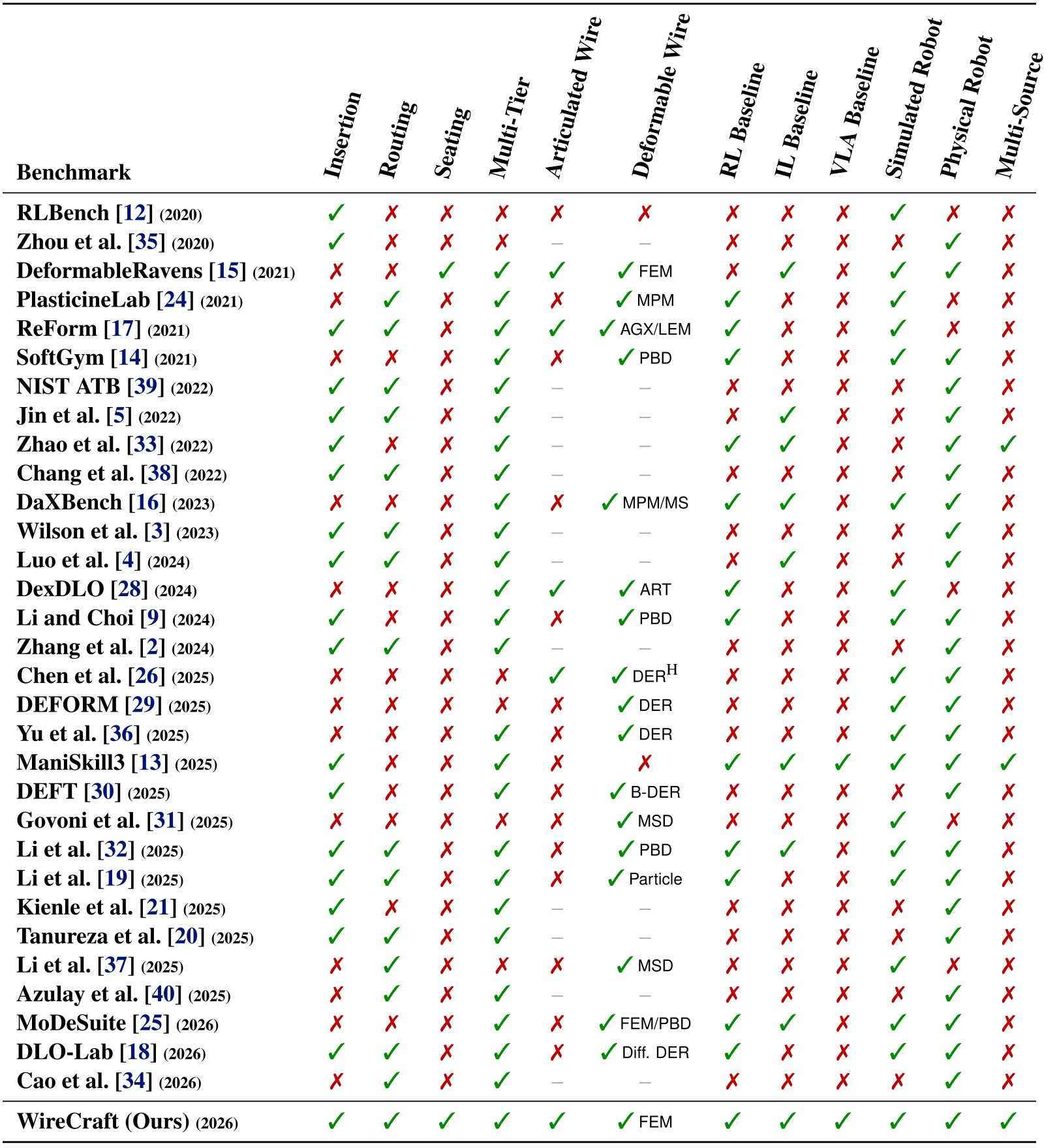
WireCraft emphasizes their combination: industrial insertion/routing/seating, two wire representations, multiple learning-policy families and simulation plus real demonstrations. The comparison table uses the authors’ feature definitions; its coverage markings are not an independent audit of every prior system. The evaluated methods are representative baselines rather than exhaustively optimized solvers.
3 WireCraft Infrastructure
3.1 WireCraft Engine
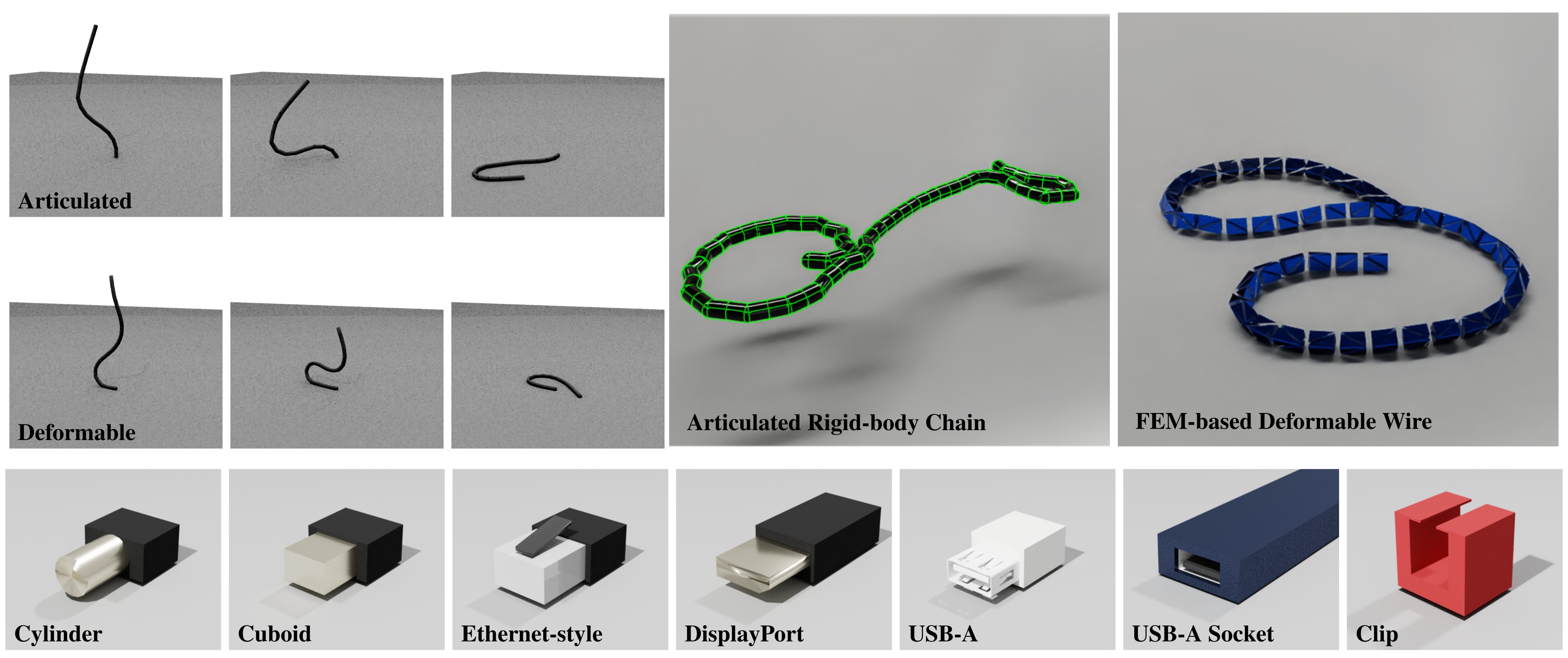
Isaac Lab 2.2.1 on Isaac Sim 4.5 supplies rendering, parallel environments and physics. Articulated wires connect rigid segments with passive six-degree-of-freedom joints; the FEM alternative models local bending, compression and contact deformation. The former supports high aggregate throughput but can suffer unstable self-contact.
RGB, optional depth, contact/force interfaces and proprioception are available, but available sensors are not necessarily policy inputs. The two wire models share task interfaces rather than calibrated dynamics; the paper does not quantitatively establish their relative real-cable accuracy.
3.2 WireCraft Assets
Wire length, radius and material or joint parameters are configurable. Printable cylindrical, cuboid and reference-style connectors vary rotational symmetry; sockets, clips and channels define fixture constraints. UR5, Franka and Trossen Stationary AI are supported in simulation, while reported hardware validation uses only UR5.
4 WireCraft Benchmark
4.1 WireCraft Tasks
Insertion combines connector alignment with trailing-wire disturbance. Routing requires seating the wire through clip openings, and channel seating constrains its extended shape. Difficulty varies with connector geometry, clip count/placement and channel curvature, while per-episode initialization changes poses.
The experiment set covers four insertion geometries, one-clip routing and straight seating. USB-A, multi-clip and curved-channel configurations are available assets or curricula, not established policy-performance results here.
4.2 WireCraft Demonstrations
Scripted state-based controllers, RL rollouts, simulation teleoperation and physical demonstrations share a LeRobot 3.0 schema. For UR5, the principal state/action vectors each contain six arm values plus the gripper, alongside wrist/side RGB and a task instruction.
The teleoperation interface is released and illustrated, but simulated teleoperation trajectories are not included in the reported policy-training datasets. Its potential for correction-rich demonstrations is therefore a capability, not an evaluated data-source benefit.
5 Experiments
Insertion reports both reaching within 2 cm and actual tip seating; reaching is not successful assembly. Routing requires clip seating, and channel success requires more than 80% of the wire inside the channel. Reported standard deviations are across evaluation or RL seeds under the specified protocols, not confidence intervals for all possible hardware conditions.
5.1 Baselines on Connector Insertion
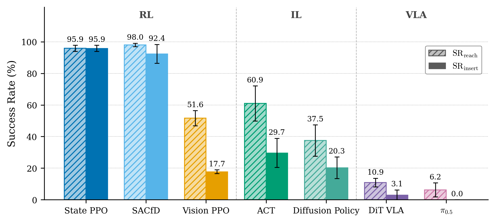
On Ethernet-style insertion with 3 mm clearance, privileged State PPO and SACfD insert at about 95.9% and 92.4%. Image-based ACT reaches/inserts at 60.9/29.7%, Diffusion Policy at 37.5/20.3%, Vision PPO at 51.6/17.7%, DiT VLA at 10.9/3.1% and π₀.₅ at 6.2/0%. Vision-based reaching itself can fail, and successful transport does not guarantee a suitable grasp or final alignment.
The methods differ in information, architectures, demonstration use and optimization budgets. Low VLA results with frozen vision components and limited fine-tuning are not an architecture-level impossibility result. The suggested pretraining-distribution explanation is not separately isolated; insertion IL/VLA checkpoint selection also uses evaluation reach scores.
5.2 RL Baselines on Diverse Connector Insertion
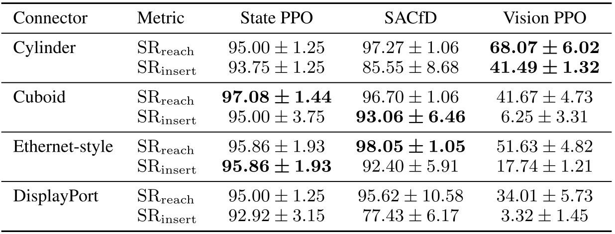
Across cylinder, cuboid, Ethernet-style and DisplayPort fixtures, State PPO insertion stays around 93–96%, while SACfD ranges from 77.43% to 93.06%. Vision PPO ranges from 3.32% on DisplayPort to 41.49% on the cylinder. The detailed table preserves both reach and insertion results.
Geometry is not a monotonic difficulty scale for every policy: Vision PPO handles Ethernet-style better than cuboid, and privileged methods do not always favor the cylinder. Fixed-orientation reward bias and shape-specific visual cues are plausible explanations, not controlled causal ablations. High state-based success demonstrates feasibility for these settings, not that control difficulty disappears generally.
5.3 Clip Routing and Channel Seating
State PPO succeeds at 95.32% on one-clip routing and 82.33% on straight seating. ACT reaches 64.06%/18.80%, and DiT VLA 39.06%/15.62%. These results extend the privileged-state versus visual-policy gap beyond insertion, but do not evaluate the harder multi-clip or curved-channel curricula.

6 Real-World Validation
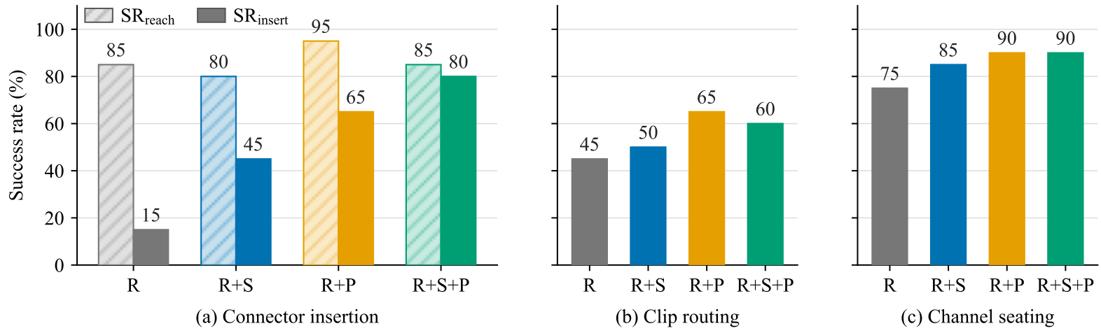
Hardware compares ACT trained on real data R, real plus scripted simulation R+S, real plus simulation RL R+P and all three R+S+P, with twenty trials per task/mixture. Insertion success is 15/45/65/80%; routing 45/50/65/60%; seating 75/85/90/90%. The strongest mixture is task-dependent; adding every source does not monotonically improve routing.
Insertion reach stays 80–95%, yet R+P reaches more often than R+S+P while seating less often. The observed grasp-pose differences suggest that a transportable grasp can be unsuitable for mating. Routing near-misses remain failures even when the wire lands closer to the clip; seating failures often originate at grasp acquisition.
All tested mixtures contain real demonstrations, after poor preliminary simulation-only transfer. The physical initialization is narrower than the simulation benchmark. Source composition and total data quantity change together, so the results demonstrate supplementation under this setup rather than isolating diversity or proving zero-shot transfer.
7 Limitations
Neither wire model is calibrated to the physical cable, their dynamic/contact behavior is quantitatively unmatched, and cross-model policy transfer is untested. Optional depth and full force/torque feedback are not evaluated; privileged insertion uses saturated fingertip contacts, and the physical force/torque sensor is unread.
Only selected tasks on one UR5 and limited wire/fixture combinations receive hardware testing. Binary success omits contact loads and wire damage. VLA outcomes depend on constrained training, and small physical trial counts cannot establish a precise universal ordering of data mixtures.
8 Conclusion
The benchmark separates task feasibility with privileged state from the difficulty of visual localization, grasp selection, deformation and fixture engagement. Its common assets and data interface enable more comparable future studies, while the current hardware results support task portability with real-data adaptation rather than physically validated wire simulation.
Acknowledgments
The work acknowledges partial support from the Republic of Korea’s industrial technology innovation program for autonomous assembly of flexible and complex components.
Appendix A Related Work
The restored thirty-two-row comparison lists twelve feature dimensions for prior environments, applied systems and WireCraft. Its definitions distinguish insertion, fixture routing and extended channel placement, as well as learning baselines, robot evaluation and multiple demonstration sources. This is a categorical author comparison, not a measured performance ranking.
Selectable transcription of PDF table (PDF reference numbering)
| Benchmark | Insertion | Routing | Seating | Multi-Tier | Articulated Wire | Deformable Wire | RL Baseline | IL Baseline | VLA Baseline | Simulated Robot | Physical Robot | Multi-Source |
|---|---|---|---|---|---|---|---|---|---|---|---|---|
| RLBench [12] (2020) | ✓ | ✗ | ✗ | ✗ | ✗ | ✗ | ✗ | ✗ | ✗ | ✓ | ✗ | ✗ |
| Zhou et al. [35] (2020) | ✓ | ✗ | ✗ | ✗ | – | – | ✗ | ✗ | ✗ | ✗ | ✓ | ✗ |
| DeformableRavens [15] (2021) | ✗ | ✗ | ✓ | ✓ | ✓ | ✓FEM | ✗ | ✓ | ✗ | ✓ | ✓ | ✗ |
| PlasticineLab [24] (2021) | ✗ | ✓ | ✗ | ✓ | ✗ | ✓MPM | ✓ | ✗ | ✗ | ✓ | ✗ | ✗ |
| ReForm [17] (2021) | ✓ | ✓ | ✗ | ✓ | ✓ | ✓AGX/LEM | ✓ | ✗ | ✗ | ✓ | ✗ | ✗ |
| SoftGym [14] (2021) | ✗ | ✗ | ✗ | ✓ | ✗ | ✓PBD | ✓ | ✗ | ✗ | ✓ | ✓ | ✗ |
| NIST ATB [39] (2022) | ✓ | ✓ | ✗ | ✓ | – | – | ✗ | ✗ | ✗ | ✗ | ✓ | ✗ |
| Jin et al. [5] (2022) | ✓ | ✓ | ✗ | ✓ | – | – | ✗ | ✓ | ✗ | ✗ | ✓ | ✗ |
| Zhao et al. [33] (2022) | ✓ | ✗ | ✗ | ✓ | – | – | ✓ | ✓ | ✗ | ✗ | ✓ | ✓ |
| Chang et al. [38] (2022) | ✓ | ✓ | ✗ | ✓ | – | – | ✗ | ✗ | ✗ | ✗ | ✓ | ✗ |
| DaXBench [16] (2023) | ✗ | ✗ | ✗ | ✓ | ✗ | ✓MPM/MS | ✓ | ✓ | ✗ | ✓ | ✓ | ✗ |
| Wilson et al. [3] (2023) | ✓ | ✓ | ✗ | ✓ | – | – | ✗ | ✗ | ✗ | ✗ | ✓ | ✗ |
| Luo et al. [4] (2024) | ✓ | ✓ | ✗ | ✓ | – | – | ✗ | ✓ | ✗ | ✗ | ✓ | ✗ |
| DexDLO [28] (2024) | ✗ | ✗ | ✗ | ✓ | ✓ | ✓ART | ✓ | ✗ | ✗ | ✓ | ✗ | ✗ |
| Li and Choi [9] (2024) | ✓ | ✗ | ✗ | ✓ | ✗ | ✓PBD | ✓ | ✗ | ✗ | ✓ | ✓ | ✗ |
| Zhang et al. [2] (2024) | ✓ | ✓ | ✗ | ✓ | – | – | ✗ | ✗ | ✗ | ✗ | ✓ | ✗ |
| Chen et al. [26] (2025) | ✗ | ✗ | ✗ | ✗ | ✓ | ✓DERH | ✗ | ✗ | ✗ | ✓ | ✓ | ✗ |
| DEFORM [29] (2025) | ✗ | ✗ | ✗ | ✗ | ✗ | ✓DER | ✗ | ✗ | ✗ | ✓ | ✓ | ✗ |
| Yu et al. [36] (2025) | ✗ | ✗ | ✗ | ✓ | ✗ | ✓DER | ✗ | ✗ | ✗ | ✓ | ✓ | ✗ |
| ManiSkill3 [13] (2025) | ✓ | ✗ | ✗ | ✓ | ✗ | ✗ | ✓ | ✓ | ✓ | ✓ | ✓ | ✓ |
| DEFT [30] (2025) | ✓ | ✗ | ✗ | ✓ | ✗ | ✓B-DER | ✗ | ✗ | ✗ | ✗ | ✓ | ✗ |
| Govoni et al. [31] (2025) | ✗ | ✗ | ✗ | ✗ | ✗ | ✓MSD | ✗ | ✗ | ✗ | ✓ | ✗ | ✗ |
| Li et al. [32] (2025) | ✓ | ✓ | ✗ | ✓ | ✗ | ✓PBD | ✓ | ✓ | ✗ | ✓ | ✓ | ✗ |
| Li et al. [19] (2025) | ✓ | ✓ | ✗ | ✓ | ✗ | ✓Particle | ✓ | ✗ | ✗ | ✓ | ✓ | ✗ |
| Kienle et al. [21] (2025) | ✓ | ✗ | ✗ | ✓ | – | – | ✗ | ✗ | ✗ | ✗ | ✓ | ✗ |
| Tanureza et al. [20] (2025) | ✓ | ✓ | ✗ | ✓ | – | – | ✗ | ✗ | ✗ | ✗ | ✓ | ✗ |
| Li et al. [37] (2025) | ✗ | ✓ | ✗ | ✗ | ✗ | ✓MSD | ✗ | ✗ | ✗ | ✓ | ✗ | ✗ |
| Azulay et al. [40] (2025) | ✗ | ✓ | ✗ | ✓ | – | – | ✗ | ✗ | ✗ | ✗ | ✓ | ✗ |
| MoDeSuite [25] (2026) | ✗ | ✗ | ✗ | ✓ | ✗ | ✓FEM/PBD | ✓ | ✓ | ✗ | ✓ | ✓ | ✗ |
| DLO-Lab [18] (2026) | ✓ | ✓ | ✗ | ✓ | ✗ | ✓Diff. DER | ✓ | ✗ | ✗ | ✓ | ✓ | ✗ |
| Cao et al. [34] (2026) | ✗ | ✓ | ✗ | ✓ | – | – | ✗ | ✗ | ✗ | ✗ | ✓ | ✗ |
| WireCraft (Ours) (2026) | ✓ | ✓ | ✓ | ✓ | ✓ | ✓FEM | ✓ | ✓ | ✓ | ✓ | ✓ | ✓ |
Appendix B DLO Physics and Simulation Details
The appendix supplies simulator versions, model-specific parameters, coupling mechanisms and an isolated throughput experiment. These details define reproducible benchmark configurations without making the two models material-equivalent.
B.1 Simulation Backend
The default physics step is 1/120 s with decimation two, yielding 60 Hz control and eight-second RL episodes. The authors also checked Isaac Sim 5.1 and several GPU models; the detailed scaling curve specifically uses an RTX A4000.
B.2 DLO Models
Both example wires are 0.4 m long, but FEM uses 3 mm radius, density 800 and a forty-resolution mesh, while the articulated model uses twelve segments, 4 mm radius and density 2000. Joint stiffness/damping and elastic modulus are different solver-native controls and should not be compared numerically as equivalent material parameters.
Connector mass is 0.01 kg, connector friction is 2, gripper-pad friction 5 and default table friction 1. The complete table retains all contact, solver, collision and material settings; their physical accuracy has not been calibrated.
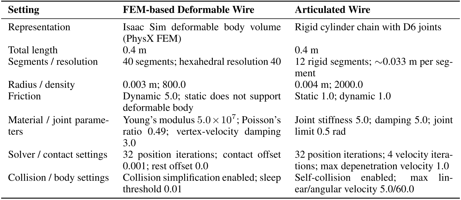
Original selectable table
| Setting | FEM-based Deformable Wire | Articulated Wire |
| Representation | Isaac Sim deformable body volume (PhysX FEM) | Rigid cylinder chain with D6 joints |
| Total length | 0.4 m | 0.4 m |
| Segments / resolution | 40 segments; hexahedral resolution 40 | 12 rigid segments; 0.033 m per segment |
| Radius / density | 0.003 m; 800.0 | 0.004 m; 2000.0 |
| Friction | Dynamic 5.0; static does not support deformable body | Static 1.0; dynamic 1.0 |
| Material / joint parameters | Young’s modulus ; Poisson’s ratio 0.49; vertex-velocity damping 3.0 | Joint stiffness 5.0; damping 5.0; joint limit 0.5 rad |
| Solver / contact settings | 32 position iterations; contact offset 0.001; rest offset 0.0 | 32 position iterations; 4 velocity iterations; max depenetration velocity 1.0 |
| Collision / body settings | Collision simplification enabled; sleep threshold 0.01 | Self-collision enabled; max linear/angular velocity 5.0/60.0 |
B.3 DLO–Connector Interaction
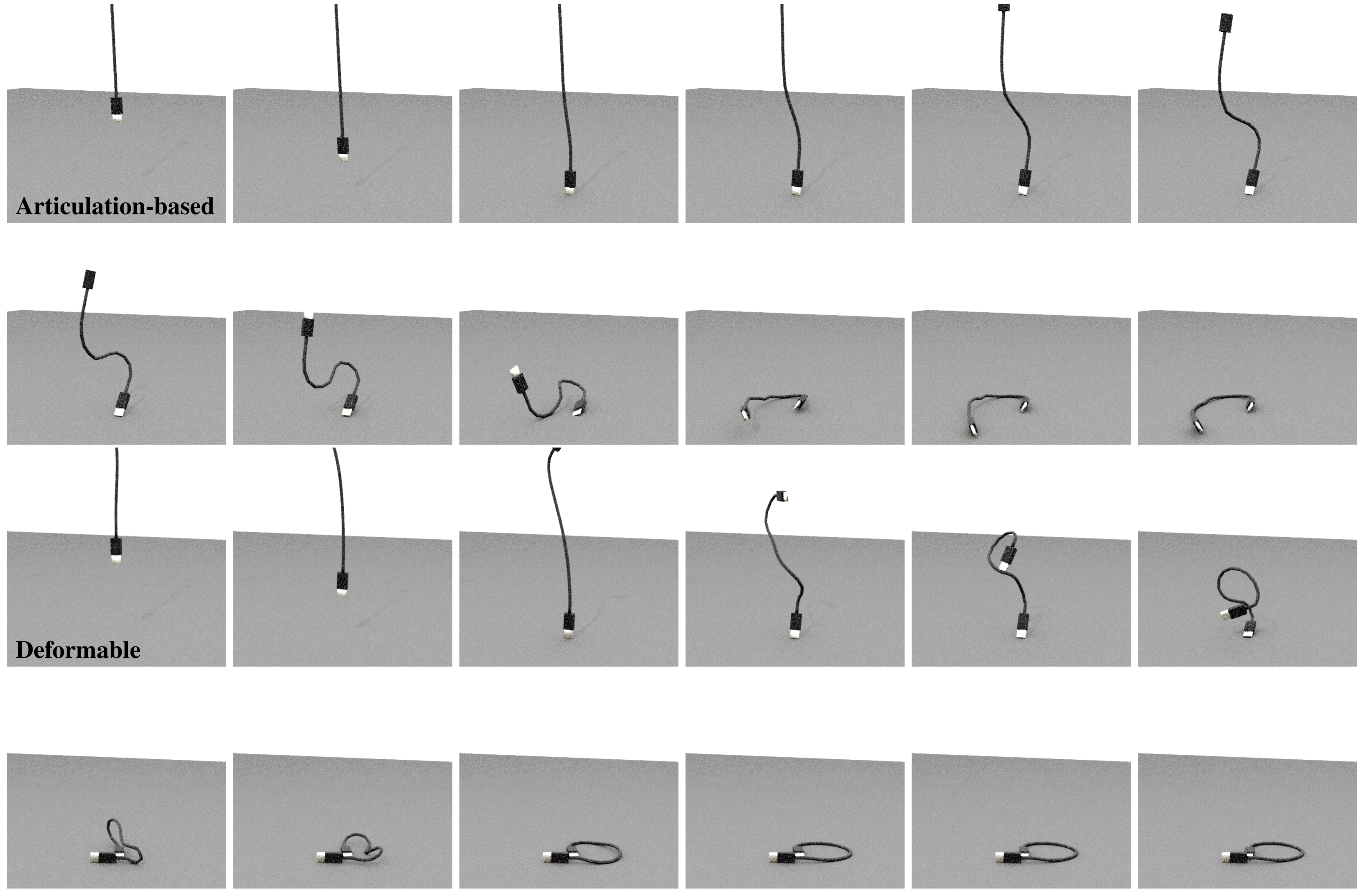
FEM endpoints use deformable-vertex attachments with 0.015 m overlap offset; articulated endpoints use fixed joints welding the connector to the terminal segment. Figure 6 preserves the entire twenty-four-frame comparison, showing the consequences of the different coupling and body models.
B.4 Computational Scaling and Throughput
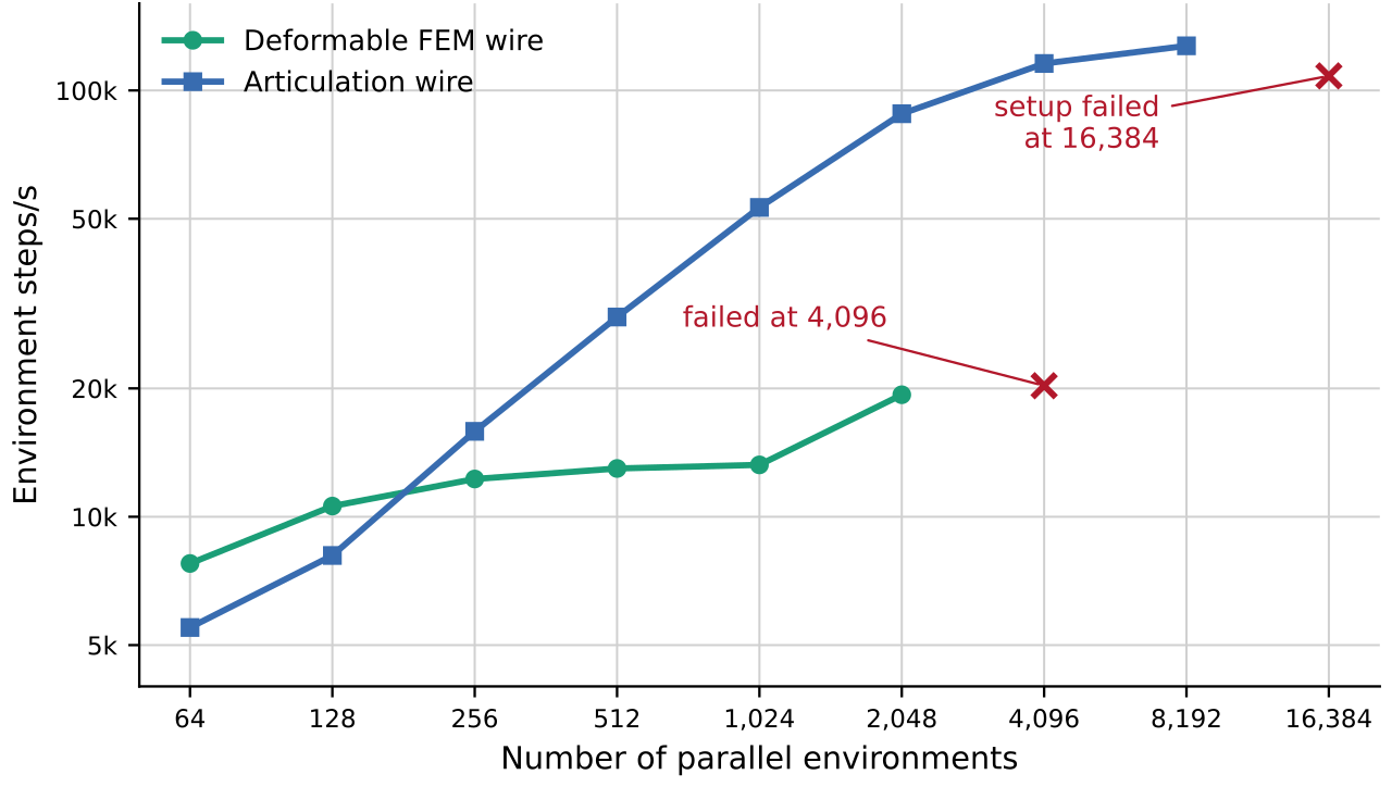
The throughput test removes robots, endpoint connectors and rendering, retaining DLO-only ground contact. Each configuration has five seconds of warmup and sixty seconds of measurement at 120 Hz physics. Articulated simulation succeeds through 8,192 environments and fails to set up at 16,384; FEM succeeds through 2,048 and fails at 4,096.
FEM is faster at the smallest counts, while the chain scales to much higher aggregate steps per second. The authors relate FEM failure to a 4,095-volume actor cap and potentially earlier fixed GPU-memory limits. This is configuration-specific physics throughput, not end-to-end rendered robot-policy speed or a fidelity-matched solver comparison.
Appendix C Task Design
C.1 Connector Insertion
Five connector assets range from axial-symmetric cylinders to cuboids, Ethernet-style, asymmetric DisplayPort and USB-A. Four appear in reported experiments; USB-A is released only as an additional asset. Geometry is fixed per task and socket clearance is a separate difficulty parameter.
C.2 Clip Routing
Routing curricula use one to three U-slot clips. Their longitudinal positions are fixed while lateral position and yaw vary; narrower openings and retaining lips add constraints. Longer routes may require re-grasping, but only the one-clip setting is quantitatively evaluated here.
C.3 Channel Seating
Five connected channel segments form a straight or bent path. Curved settings allow up to ±20° relative rotation per joint; the policy must position the wire body, not just move its endpoint near a goal. Reported baseline and hardware results use straight channels.
C.4 Randomization
The randomization table specifies connector drop height, roll/pitch/yaw and planar offsets, socket position, clip lateral/yaw ranges and optional channel bends. Insertion RL uses connector x/y offsets of ±5/±15 cm, socket y/z ranges of 28/15 cm and a 6–11 cm settling drop. Scripted and teleoperation collection use different planar ranges, so dataset-generation settings should not be mistaken for the RL benchmark distribution.
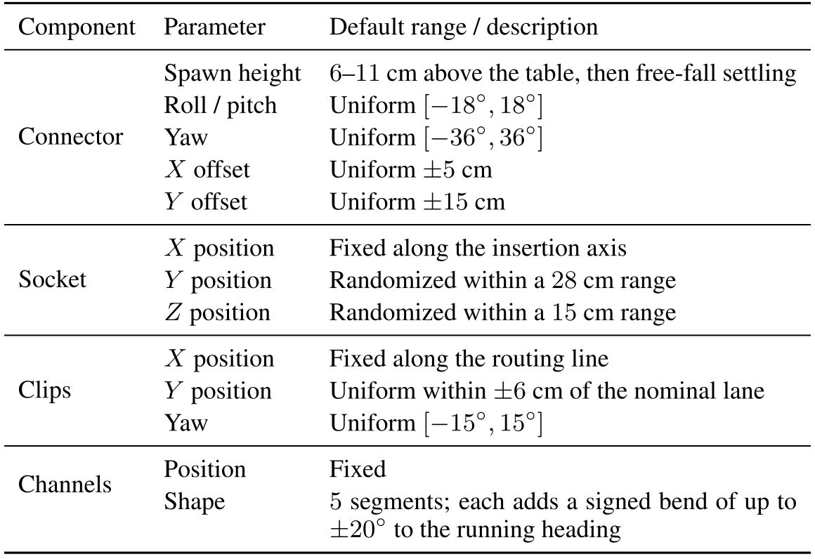
Original selectable table
| Component | Parameter | Default range / description |
| Connector | Spawn height | – cm above the table, then free-fall settling |
| Roll / pitch | Uniform | |
| Yaw | Uniform | |
| offset | Uniform cm | |
| offset | Uniform cm | |
| Socket | position | Fixed along the insertion axis |
| position | Randomized within a cm range | |
| position | Randomized within a cm range | |
| Clips | position | Fixed along the routing line |
| position | Uniform within cm of the nominal lane | |
| Yaw | Uniform | |
| Channels | Position | Fixed |
| Shape | segments; each adds a signed bend of up to to the running heading |
C.5 Control Modes
Controllers expose direct joint targets, Cartesian pose deltas or Cartesian translation with fixed orientation. Differential inverse kinematics converts Cartesian commands into the common joint-target interface, with a gripper command in every mode. Fixed orientation suits seating; insertion and routing require orientation control.
Appendix D Scripted Policy
A vectorized finite-state machine advances through approach, grasp and task phases after pose tolerances and dwell conditions are met. It clips pose errors into Cartesian delta commands and snapshots relevant frames at grasp time, preventing wire motion from continually moving the intended placement reference.
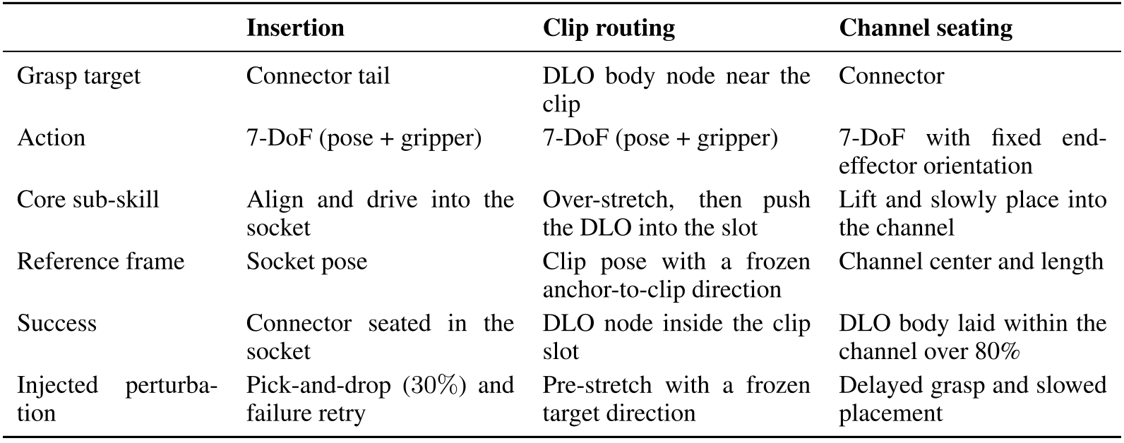
Original selectable table
| Insertion | Clip routing | Channel seating | |
| Grasp target | Connector tail | DLO body node near the clip | Connector |
| Action | 7-DoF (pose + gripper) | 7-DoF (pose + gripper) | 7-DoF with fixed end-effector orientation |
| Core sub-skill | Align and drive into the socket | Over-stretch, then push the DLO into the slot | Lift and slowly place into the channel |
| Reference frame | Socket pose | Clip pose with a frozen anchor-to-clip direction | Channel center and length |
| Success | Connector seated in the socket | DLO node inside the clip slot | DLO body laid within the channel over 80% |
| Injected perturbation | Pick-and-drop () and failure retry | Pre-stretch with a frozen target direction | Delayed grasp and slowed placement |
D.1 Insertion
Insertion grasps the connector tail, lifts, aligns the held connector to the socket, advances and releases. A 30% pick-and-drop perturbation creates recovery examples, and unsuccessful seating can trigger up to two approach retries. Pitch/grasp-offset randomization and local speed reductions diversify the trajectories.
D.2 Clip Routing
Routing grasps the wire body nearest the clip, with gripper orientation aligned to its local tangent. It lifts and rotates, over-stretches along a frozen anchor-to-clip direction, pulls back to release tension, then descends past the retaining lip. Grasping the connector would fail geometrically because it is wider than the slot.
D.3 Channel Seating
Seating grasps the connector after a settling delay, lifts gently and follows the channel at reduced speed with fixed orientation. Fine action scaling and gradual path descent aim to avoid snagging; following a path permits both straight and curved task definitions.
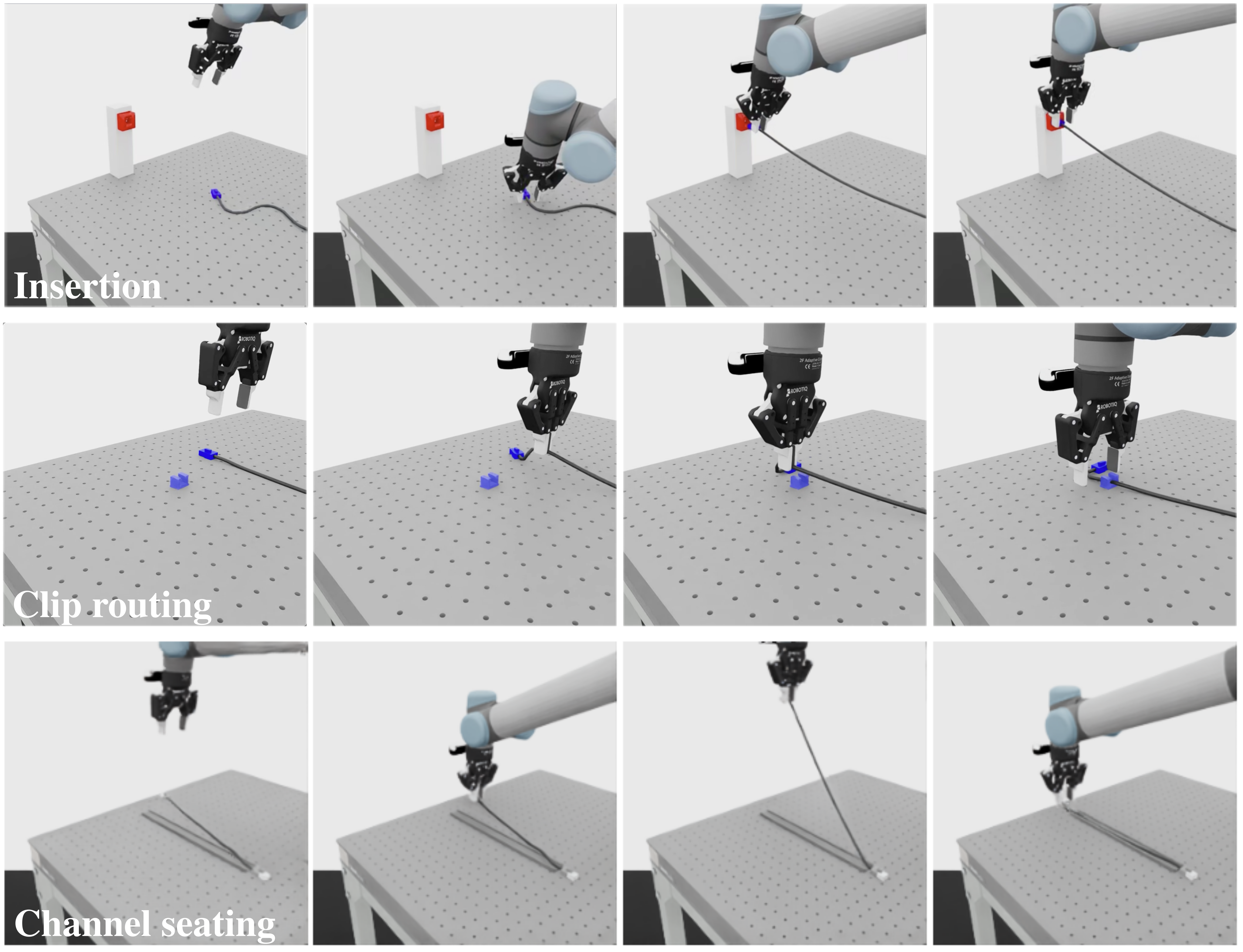
D.4 Scripted Demonstrations
Figure 8 keeps all twelve snapshots of the three scripted task rollouts, including grasp, transport and fixture engagement.
Appendix E RL Experiment Detail
E.1 State-based RL
Privileged insertion PPO and SACfD share state, action and shaped reward, with algorithm-specific normalization and networks. Routing and seating reuse PPO hyperparameters with task-specific observations/rewards. Reported RL means and standard deviations use three seeds.
Observation.
The forty-two-dimensional insertion state includes joint/gripper positions and velocities, end-effector pose, two fingertip contacts, connector/socket/seated-target geometry and gate/error scalars. This exposes goal-relative information unavailable to an RGB-only actor.
Action and control.
A six-dimensional Cartesian delta plus gripper command is clipped to [−1,1] and scaled by 0.01 before differential inverse kinematics. The RL setting runs at 60 Hz for eight-second episodes; imitation-learning evaluation later specifies its own 800-step horizon.
Reward.
The common reward shapes reaching, grasping, bringing, alignment and orientation, with a large insertion-depth progress term and seated bonus. Table/gripper and action penalties discourage undesirable motion. Success under this detailed privileged reward does not measure how easily the task can be learned from sparse visual feedback.
Networks.
PPO uses 256/128/64-unit ELU actor and critic networks. SACfD uses 256/256-unit actor and twin critics, about 150,000 scripted transitions, a 50% demonstration replay ratio and an annealed behavior-cloning weight. The two full hyperparameter tables retain the exact schedules and budgets.
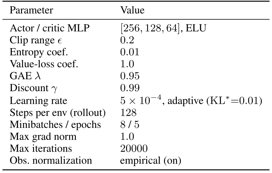
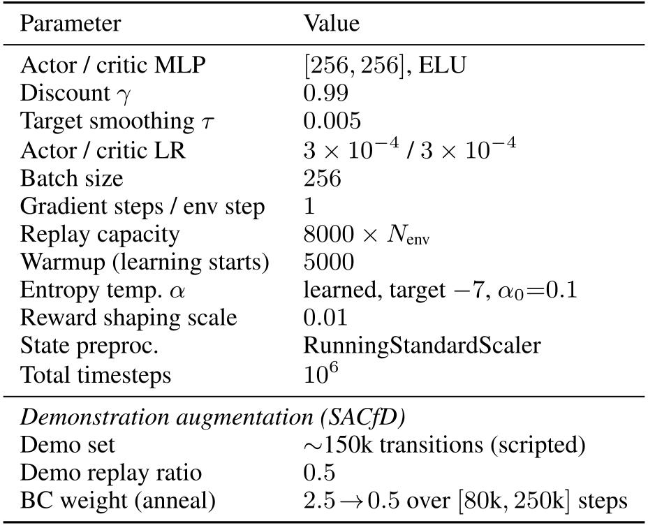
Original selectable table
| Parameter | Value |
| Actor / critic MLP | , ELU |
| Discount | |
| Target smoothing | |
| Actor / critic LR | / |
| Batch size | |
| Gradient steps / env step | |
| Replay capacity | |
| Warmup (learning starts) | |
| Entropy temp. | learned, target , |
| Reward shaping scale | |
| State preproc. | RunningStandardScaler |
| Total timesteps | |
| Demonstration augmentation (SACfD) | |
| Demo set | 150k transitions (scripted) |
| Demo replay ratio | |
| BC weight (anneal) | over steps |
E.2 Vision PPO
Design rationale.
Vision PPO first behavior-clones a visual actor from state-policy rollouts, then applies online PPO. This uses privileged teachers and pretrained visual representations; it is not vision-only learning from scratch.
Architecture.
The actor receives two 224×224 RGB images and fourteen proprioceptive values; the critic retains the forty-two-dimensional privileged state. A DINOv2 backbone with eight pooling queries per camera supplies the actor features. During PPO both backbone and attention pool are frozen; only the output projection, action noise and critic train. The critic starts from the converged state policy.
Hyperparameters.
Visual fine-tuning uses sixty-four environments and six hundred iterations, with clip 0.1, target KL 0.005, learning rate 10⁻⁴ and small initial action noise. It removes entropy bonuses and observation normalization and reduces the value-loss weight. Thus its budget and trainable modules differ markedly from privileged PPO.
E.3 RL Rollout Demonstrations
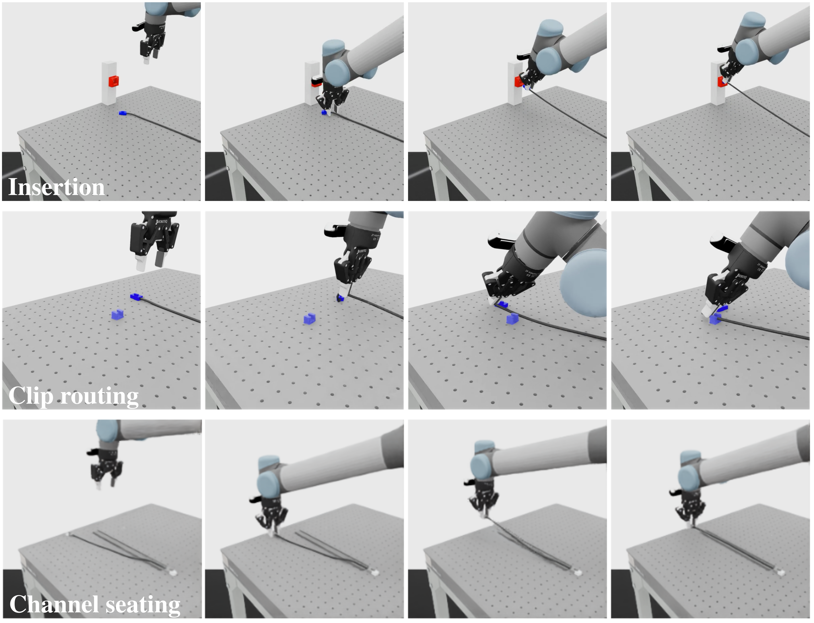
Figure 9 retains all twelve State-PPO snapshots, including a clip-routing error and recovery. These illustrate closed-loop trajectory characteristics without quantifying a general recovery rate.
Appendix F Connector-Insertion IL/VLA Experimental Details
F.1 Dataset
The four insertion IL/VLA baselines share one thousand scripted trajectories, two RGB views and seven-dimensional UR5 joint/gripper state and actions. Sharing this dataset does not equalize pretrained knowledge, architecture or training exposure.
F.2 Policy Training Configurations
ACT trains for 100k steps, Diffusion Policy 200k, DiT VLA 300k and π₀.₅ 50k, with different batch sizes, horizons and executed action chunks. DiT uses frozen CLIP image/text conditioning; π₀.₅ freezes the vision tower while adapting the action expert and language adapter. The full configuration table is retained.
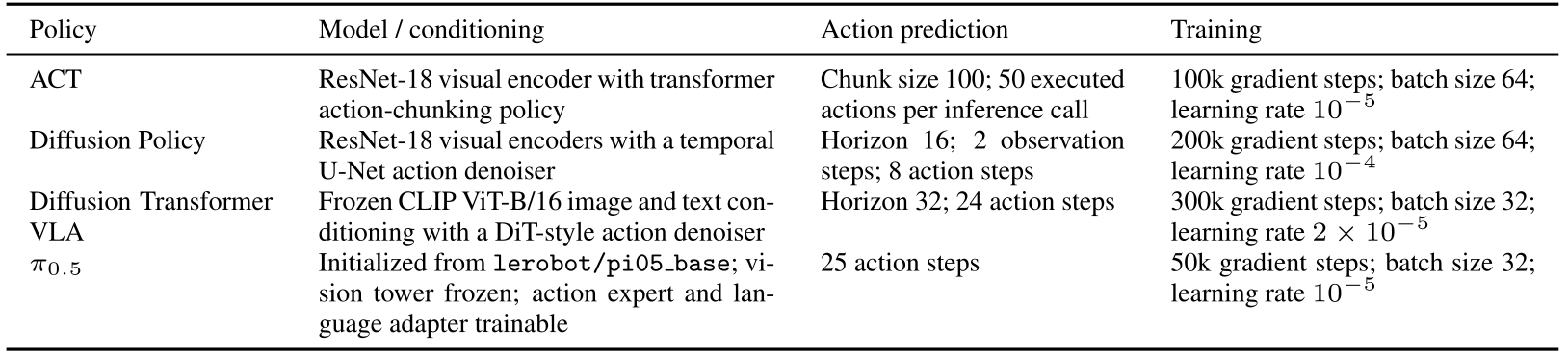
Original selectable table
| Policy | Model / conditioning | Action prediction | Training |
| ACT | ResNet-18 visual encoder with transformer action-chunking policy | Chunk size 100; 50 executed actions per inference call | 100k gradient steps; batch size 64; learning rate |
| Diffusion Policy | ResNet-18 visual encoders with a temporal U-Net action denoiser | Horizon 16; 2 observation steps; 8 action steps | 200k gradient steps; batch size 64; learning rate |
| Diffusion Transformer VLA | Frozen CLIP ViT-B/16 image and text conditioning with a DiT-style action denoiser | Horizon 32; 24 action steps | 300k gradient steps; batch size 32; learning rate |
| Initialized from lerobot/pi05_base; vision tower frozen; action expert and language adapter trainable | 25 action steps | 50k gradient steps; batch size 32; learning rate |
F.3 Checkpoint Selection
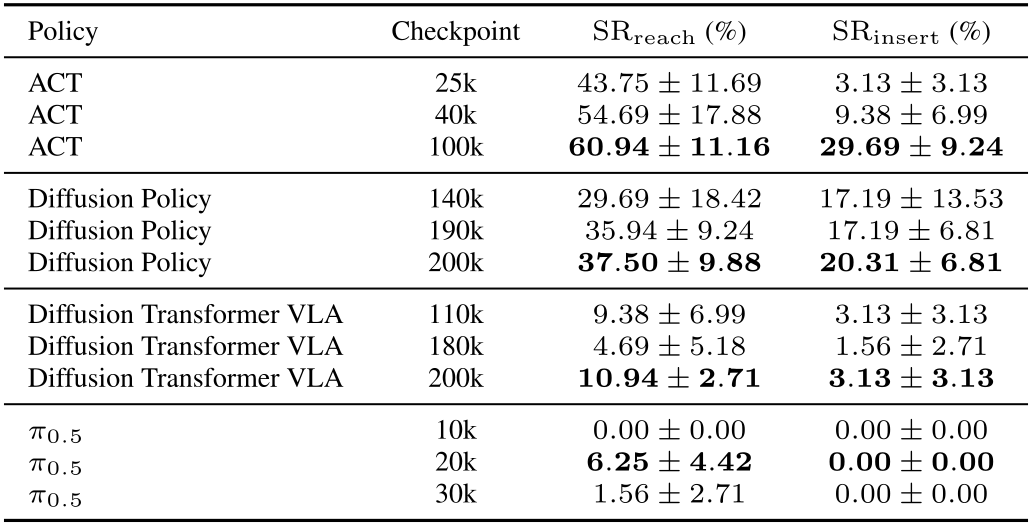
Three checkpoints per policy are retained using reach success on evaluation rollouts, rather than an independent validation split. The displayed best-observed results are optimistic under this selection procedure. Insertion success comes from the same selected checkpoint and is not independently optimized, but its correlation with reach does not make selection independent of test performance.
F.4 Evaluation Protocol
Each retained checkpoint receives four seeds with sixteen rollouts each, recording reach and insertion from the same trajectory over an 800-simulator-step horizon. All twelve checkpoint rows are preserved: ACT improves substantially by 100k, while π₀.₅ has zero insertion success for all three retained checkpoints. These four evaluation seeds differ from the three-seed RL/routing/seating protocols.

Appendix G Clip Routing and Channel Seating Experimental Details
Datasets.
Routing uses 1,600 scripted trajectories and straight seating one thousand, shared between ACT and DiT VLA within each task.
Training.
ACT trains for 100k steps with batch 64 and executes fifty of each predicted hundred-action chunk. DiT trains for 300k with batch 32, two observations, horizon thirty-two and twenty-four executed actions. All four training runs use seed 1000; evaluation-seed variation does not measure training-seed variability.
Checkpoint selection and evaluation.
These tasks evaluate the final training checkpoint over three evaluation seeds. Their selection protocol is therefore different from the insertion study’s best reach-selected checkpoints.
Appendix H Real-World Validation
The hardware study examines whether matched simulation data supplement real demonstrations. It tests ACT on three physical tasks using four real-containing mixtures after poor preliminary zero-shot simulation-only results.
H.1 Setup
Physical setup.
UR5 uses a Robotiq 2F-85 gripper and two RealSense D405 RGB views, with a 6 mm HDMI cable for insertion/routing and 10 mm cord for seating. ACT runs at 30 Hz using RGB and proprioception; neither depth nor the mounted force/torque sensor is used. Simulation matches its tool offset, cameras and task-board appearance.
Task initialization.
The insertion connector starts within 3×3 cm and the socket is fixed. Routing places one clip 2–5 cm from the wire; seating fixes one endpoint and starts the other 2–5 cm from the channel. These restricted setups limit direct comparison to the broader simulation randomization.
Bridging the sim-to-real visual gap.
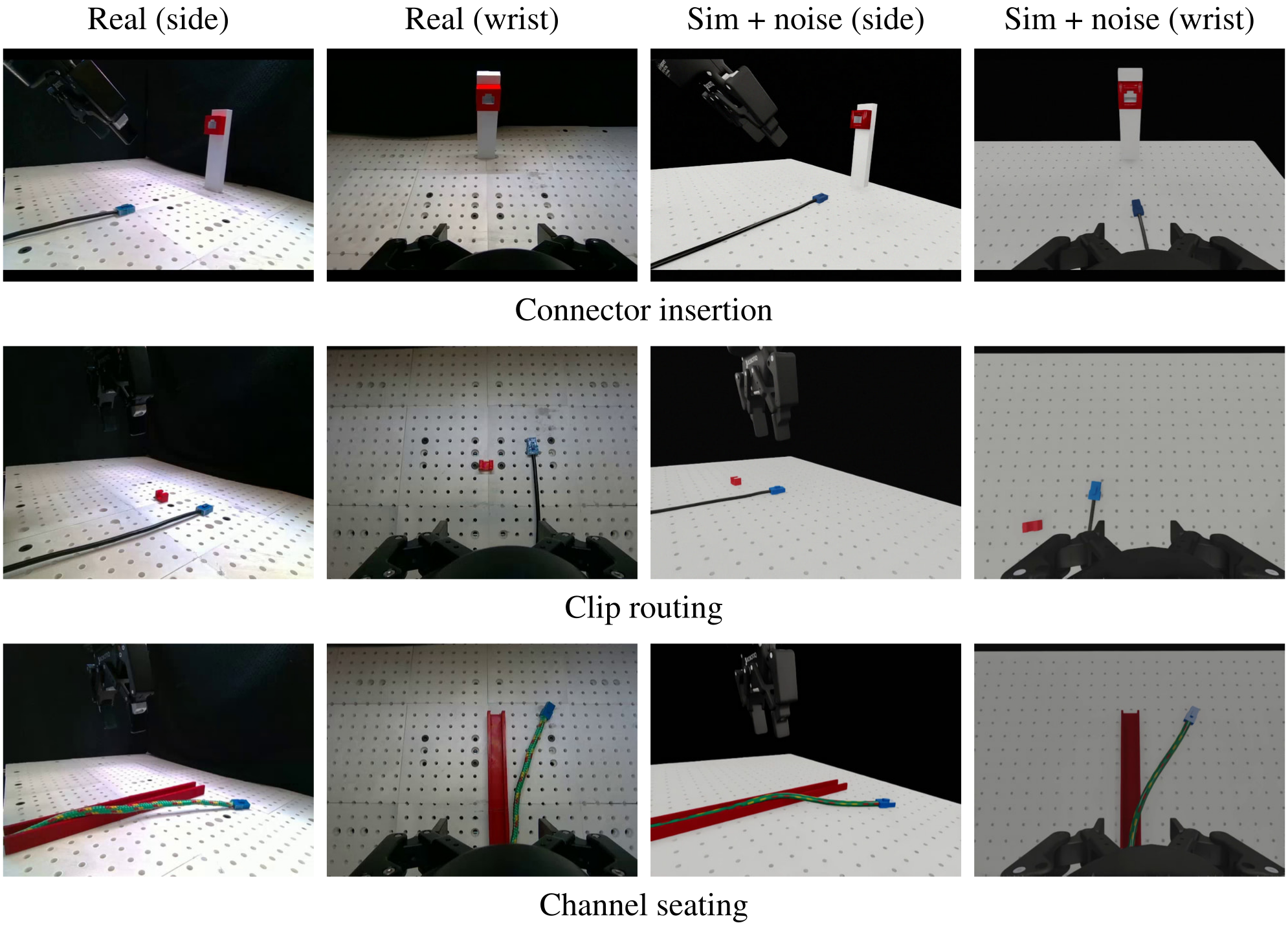
Only simulated training frames receive brightness/contrast factors in [0.85,1.15] and Gaussian noise with standard deviation up to 0.015 on normalized pixels. Real training images and evaluation inputs are unaugmented. Figure 10 preserves all twelve domain/view/task examples.
H.2 Protocol
Data sources.
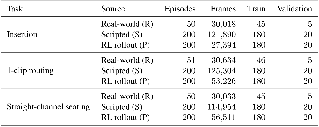
Each task has fifty real episodes, except routing with fifty-one, plus two hundred scripted and two hundred RL episodes. Every tenth episode is held out, giving five real validation episodes per task. Full frame counts and source-specific train/validation splits are preserved in Table 12.
Training.
Every mixture trains ACT for 80k steps, batch sixteen, learning rate 10⁻⁵ and seed 1000. ImageNet-initialized ResNet-18 encoders feed hundred-action predictions, with fifty actions executed per inference. A common update budget does not make the amount or distribution of training data equal.
Checkpoint selection.
Checkpoints saved every 5k steps are selected by masked normalized L1 action loss on only the five held-out real episodes, including mixed-data policies. Selected steps vary by mixture and task. Real-only normalization statistics include those held-out episodes, so the preprocessing split is not strictly independent; a small action-loss validation set also does not directly optimize physical success.
H.3 Results and Analysis
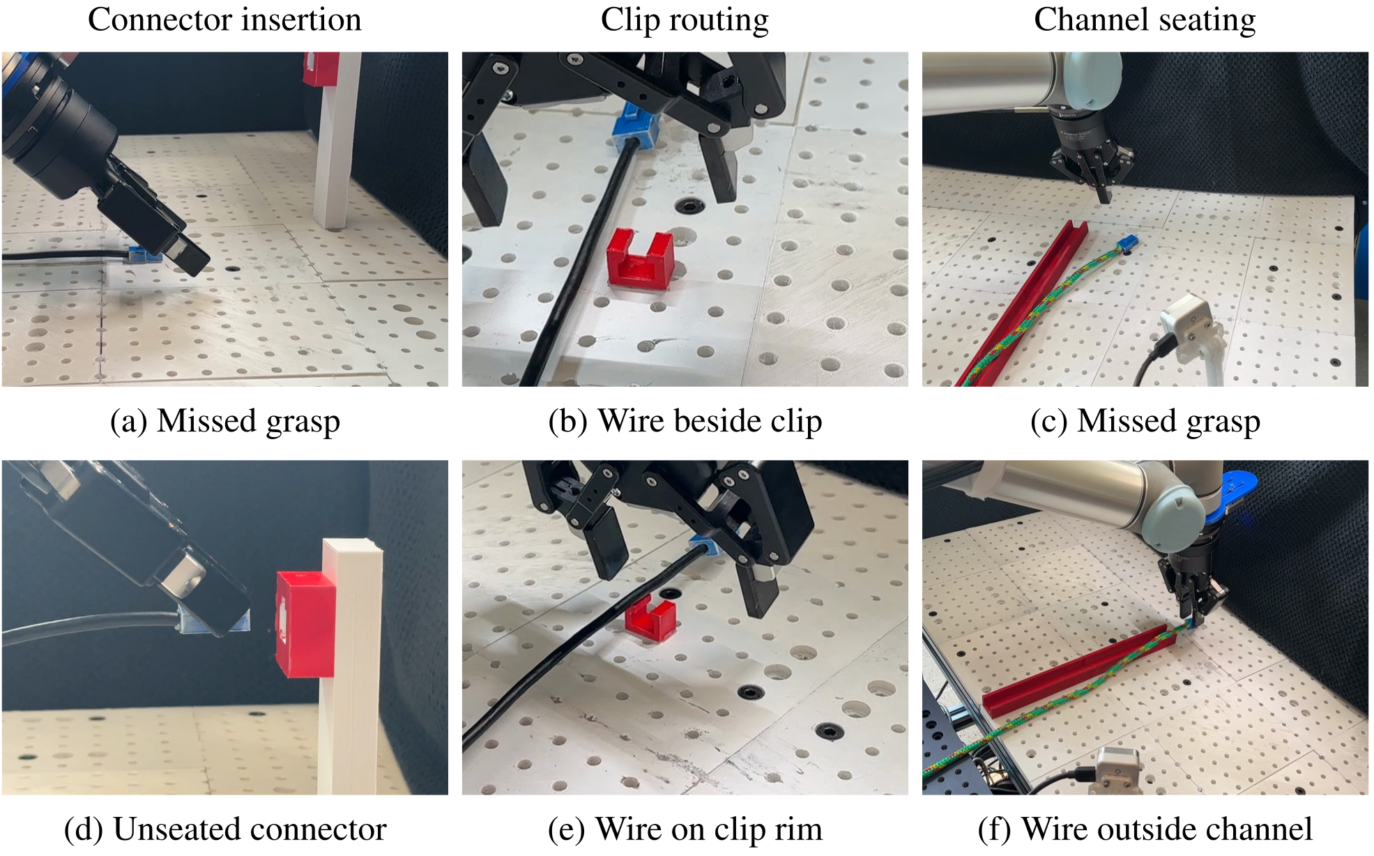
The full failure montage distinguishes missed grasps, unsuitable connector alignment, clip misses and incomplete body placement. These observations explain candidate bottlenecks but do not provide independent causal ablations.
Connector insertion.
Insertion can fail during pickup or after reaching the socket because the connector’s pose within the grasp prevents seating. Transport success and an insertion-compatible grasp are different requirements.
Clip routing.
Routing may release beside the clip or leave the wire resting on its lip. Reaching the fixture is insufficient when the wire is not actually seated.
Channel seating.
Seating failures include missed endpoint grasps and portions of the wire remaining outside the channel. Source trajectories also differ: human episodes contain corrections, scripts are slower and varied, and collected RL rollouts run at half their original policy speed.
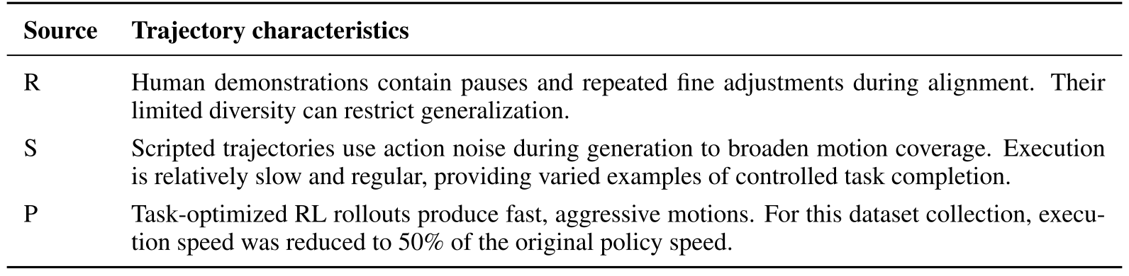
Original selectable table
| Source | Trajectory characteristics |
| R | Human demonstrations contain pauses and repeated fine adjustments during alignment. Their limited diversity can restrict generalization. |
| S | Scripted trajectories use action noise during generation to broaden motion coverage. Execution is relatively slow and regular, providing varied examples of controlled task completion. |
| P | Task-optimized RL rollouts produce fast, aggressive motions. For this dataset collection, execution speed was reduced to 50% of the original policy speed. |
Limitations.
Twenty trials imply five-percentage-point success increments: 65% versus 60% routing is only one trial. A single robot, narrow initialization and changing data sizes preclude a definitive general ranking or an isolated source-diversity effect.
Appendix I Teleoperation Data Collection
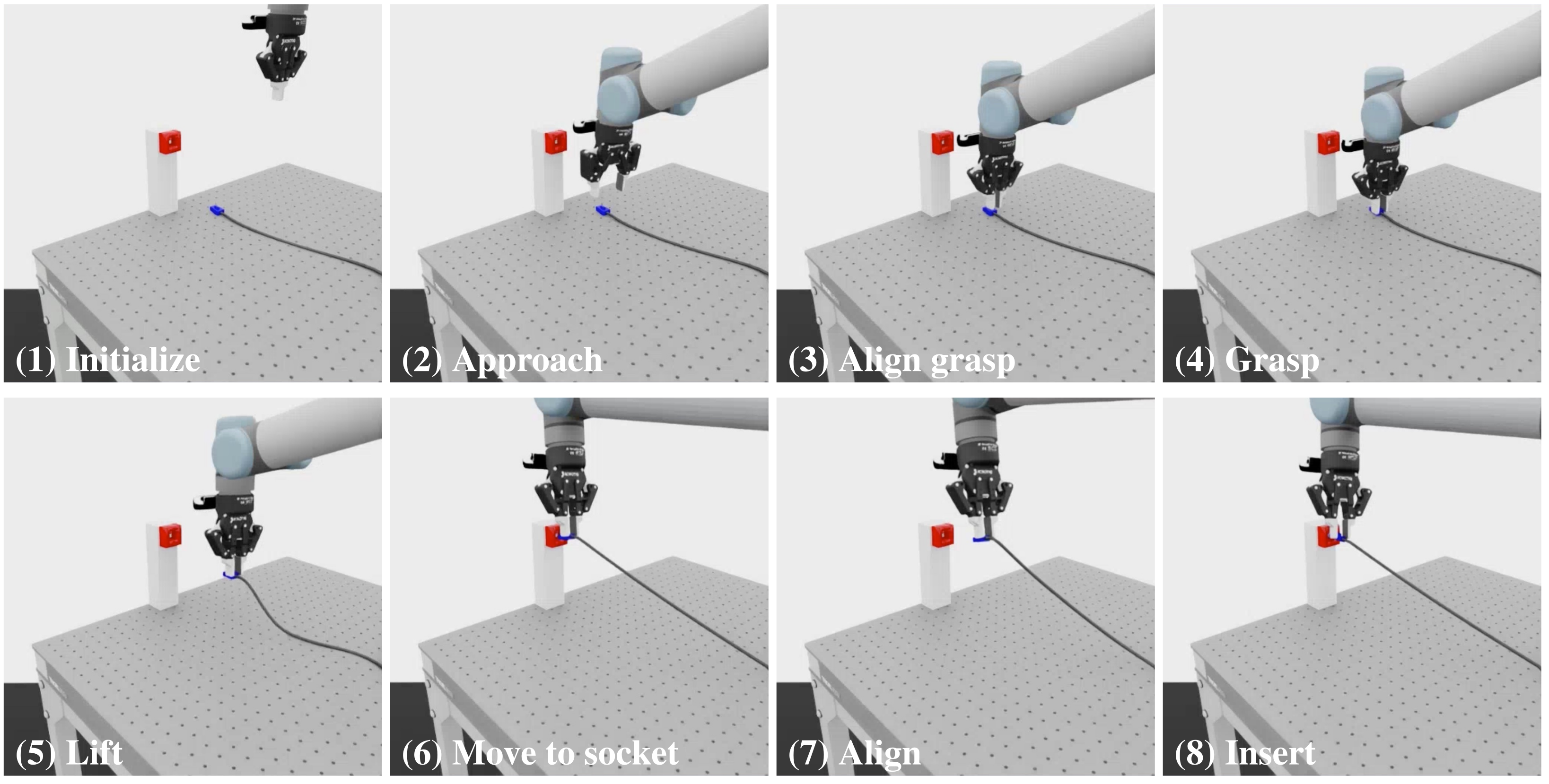
SpaceMouse, Meta Quest wrist/pinch control or combined desktop-control/VR-viewing modes produce Cartesian deltas, resolved by inverse kinematics to joint targets. Recorded actions are those applied joint targets, not raw device inputs. The common schema also stores both cameras, robot state, end-effector pose, timestamps, episode index and task label.
The eight-stage demonstration preserves repeated grasp/alignment attempts caused by limited visual cues and absent haptic feedback. Simulation teleoperation tools are available, but systematic collected-data filtering and policy training with those trajectories remain future work.
Equation