At a glance
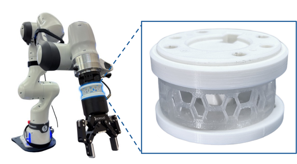
BiFlex is a passive wrist whose printed honeycomb structure stays relatively stiff below a designed buckling load and becomes compliant above it. A universal joint constrains rotation to two bending directions. Three versions support different grippers, targeting less than 1 cm fingertip deflection for objects up to 500 g. Bench and manipulation tests demonstrate a useful precision–compliance tradeoff, with no added wrist actuators or sensing needed to switch stiffness.
I Introduction
Uncertain object and surface geometry can make position-controlled rigid arms generate large contact forces. Constant compliance helps contact but sacrifices placement precision; actively variable stiffness adds hardware and control complexity. BiFlex instead sets the transition mechanically: ordinary manipulation stays below the buckling threshold, while stronger contact induces passive bending. The contribution is a tunable structure, approximate design analysis, and tests across three grippers—not a general certification of safe interaction.
II Related Work
Actuated wrists use motors, tendons, or pneumatics to change stiffness continuously. Underactuated designs can switch between two modes but still need powered locking or switching. BiFlex removes that active mechanism. Its tradeoff is that stiffness changes with the applied load and manufactured geometry, rather than being independently commanded during a task.
III BiFlex Wrist Design
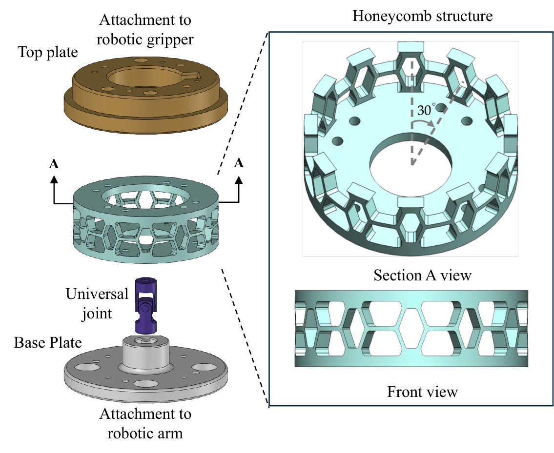
The wrist combines a buckling honeycomb, a central universal joint, and customizable mounting plates. The intended behavior is small elastic deformation during precision motion, larger bending under contact, and recovery after unloading. The universal joint suppresses axial rotation while allowing two bending degrees of freedom.
III-A Buckling Honeycomb Structure
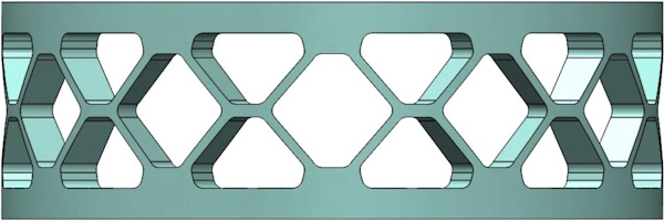
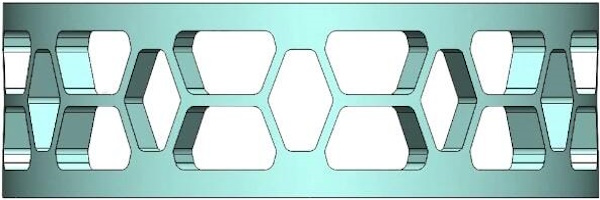
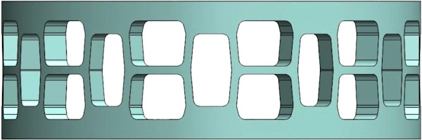
Twelve modules are distributed around the wrist. The design is at most 40 mm tall including adapters, with a roughly 21 mm flexible module and up to 40° bending. A honeycomb offers more tuning variables than the initially tested single-beam structure. The diagonal beam angle and width control both pre-buckling stiffness and the load at which the compliant regime begins. Rotational symmetry is a design aim; the central joint also helps constrain unwanted yaw.
III-B Analysis of the Honeycomb Buckling Behavior
The analysis treats one module under vertical load, assumes symmetric force sharing, neglects the force perpendicular to diagonal beams, and models beams using axial stiffness and a critical buckling load. It derives equivalent stiffness from diagonal and central beam deformation, then assumes the diagonal beams buckle first and trigger module buckling. The preserved equations show how geometry and Young’s modulus determine the transition. Beam width and diagonal angle are the principal tuning variables. These simplified relations guide fabrication; they are not an exact model of the full printed three-dimensional structure.
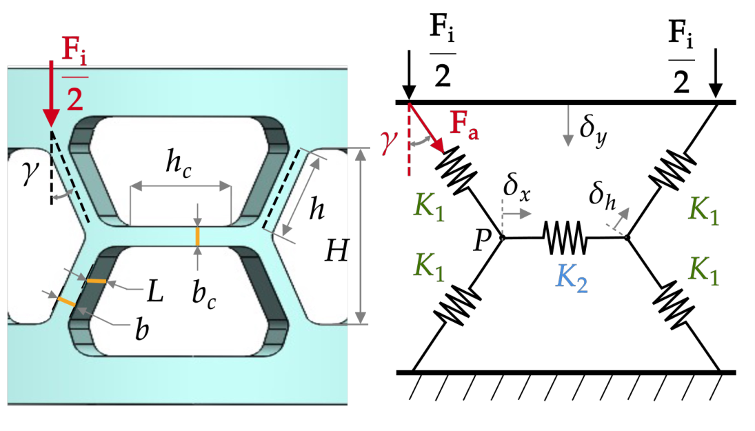
Equations 1–5
| (1) |
| (2) |
| (3) |
| (4) |
| (5) |
IV Instantiation to Different Robotic Grippers
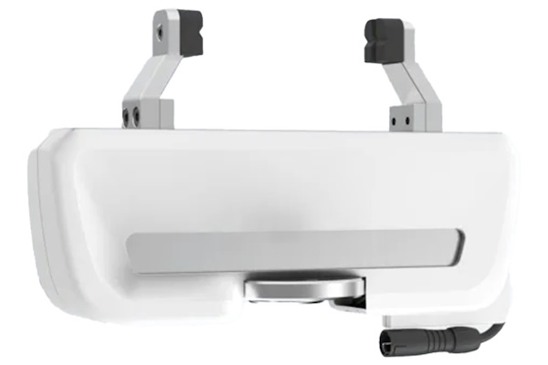
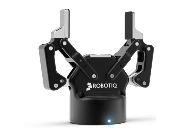
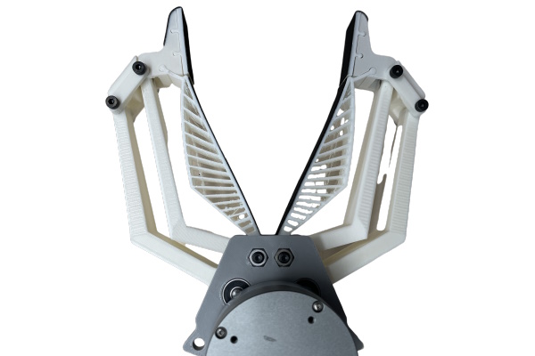
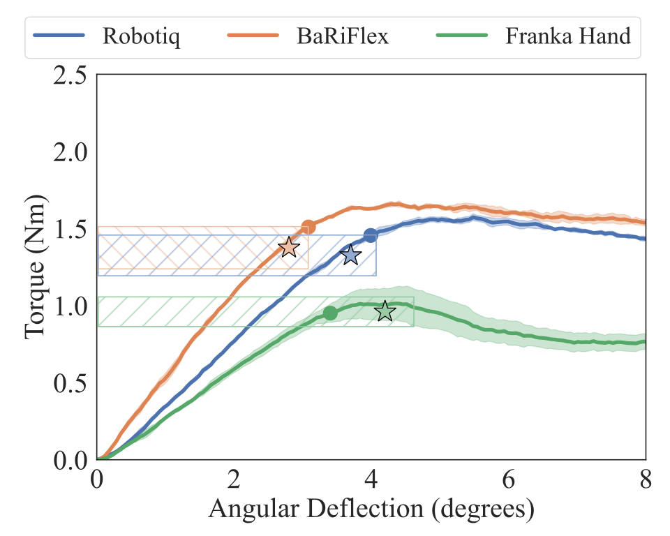
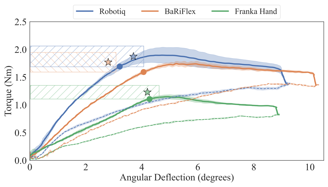
Versions for the Franka Hand, Robotiq 2F-85, and BaRiFlex account for different gripper masses and lever arms. The target is a 500 ± 50 g supported object with less than 1 cm fingertip displacement; acceptable buckling torque is within 10% of the design value. TPU-95A forms the flexible honeycomb, and PLA forms the customized plates. Total printing takes about 10 hours, including four for the honeycomb. Table I retains dimensions and selected beam parameters for each gripper.
| Gripper dimensions | Buckling point | BiFlex parameters | ||||||||||||||||
|
|
|
|
|
| |||||||||||||
| Franka | 0.70 | 135 | 0.96 | 4.20 | 0.90 | 50 | ||||||||||||
| Robotiq | 1.10 | 155 | 1.325 | 3.70 | 1.00 | 20 | ||||||||||||
| BariFlex | 0.75 | 205 | 1.378 | 2.80 | 1.20 | 5 | ||||||||||||
V Characterization
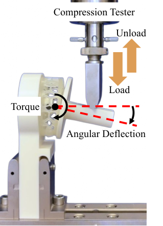
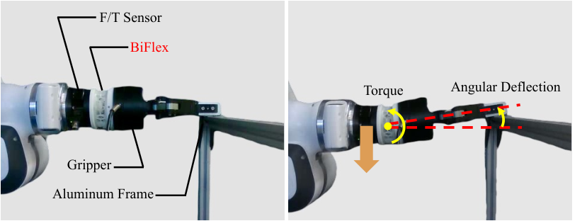
A compression machine loads a cantilever attached to each wrist; force and displacement are converted to torque and angle. Three tests per wrist are averaged. Curves rise approximately linearly before leveling after buckling. Measured angle/torque pairs are 3.06°/1.51 Nm for BaRiFlex, 3.99°/1.45 Nm for Robotiq, and 3.40°/0.95 Nm for Franka, within the stated design bounds. The buckling point is an operational estimate from an 80%-torque interpolation line and the plateau, rather than a directly observed binary switch.
VI Experimental Evaluation
Experiments separately test contact-load mitigation, surface following, placement accuracy, and grasping with a table constraint. These are bounded demonstrations using a Franka arm and selected grippers, not exhaustive tests of impact, fatigue, or human contact.
VI-A Mitigation of Contact Wrenches: Pressing Test
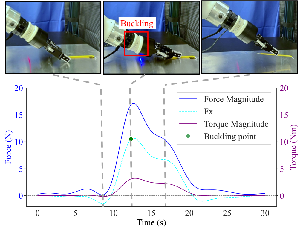
Each gripper presses against a frame until the wrist bends 10°, then unloads; a six-axis sensor measures transmitted forces and torques over three trials. Franka and Robotiq buckling points fall within the 10% design tolerance. BaRiFlex deviates, plausibly because the soft hand adds deformation that the wrist-only model omits. The authors’ 15 N threshold is a force threshold, although one sentence incorrectly calls it a torque margin. Results support load reduction under this pressing setup.
VI-B Adaptation in Contact-Rich Interaction: Wiping Test
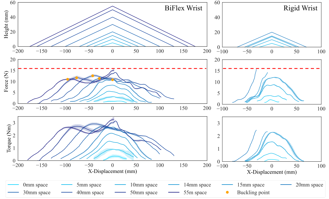
With the same stiff position controller, a Robotiq hand wipes 30° triangular slopes using a 5 mm sponge. BiFlex traverses heights up to 50 mm while staying below the experiment’s 15 N force cutoff; a rigid connection reaches only 14 mm. Buckling starts for triangles of at least 20 mm, while lower profiles use the stiffer regime. This demonstrates useful passive adaptation without force-feedback control for these surfaces.
VI-C Maintaining Accuracy: Pick-and-Place Test
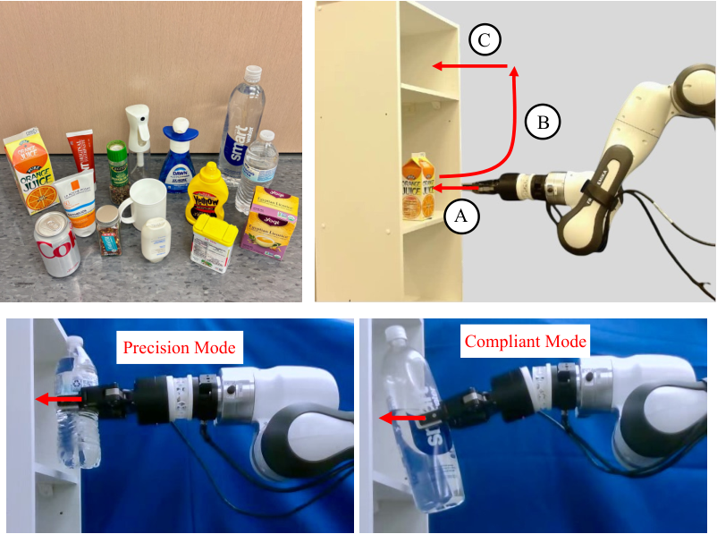
Fifteen household objects are tested with three placement attempts each. Fourteen objects below 500 g are placed without the defined shelf-contact failure. A 600 g water bottle triggers buckling and more than 10 mm fingertip displacement, causing shelf contact. The test therefore illustrates the designed load boundary as well as successful placement below it; it does not establish precision for arbitrary payloads, speeds, or orientations.
VI-D Grasping with Environmental Constraints
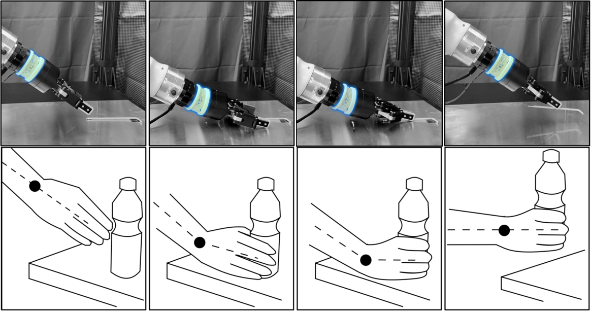
A hex wrench is grasped by sliding fingers against the table. Commanded grasp heights range from the true height to 50 mm below the surface in 5 mm steps. BiFlex succeeds throughout the tested range and recovers after lifting. The rigid wrist succeeds only at the true height and 5 mm below before exceeding the force limit. The table supplies the geometric constraint, while wrist compliance absorbs the commanded height error.
VII Discussion and Conclusion
Passive buckling can combine useful free-space precision with contact compliance in a compact replaceable wrist. Remaining limitations include low-frequency oscillations during wiping, deviations from universal-joint tolerances, and material wear that may change stiffness over time. Replacing the printed honeycomb is practical but does not eliminate those effects. Broader safety, durability, and dynamic-load claims require further evaluation.