Overview
At a glance
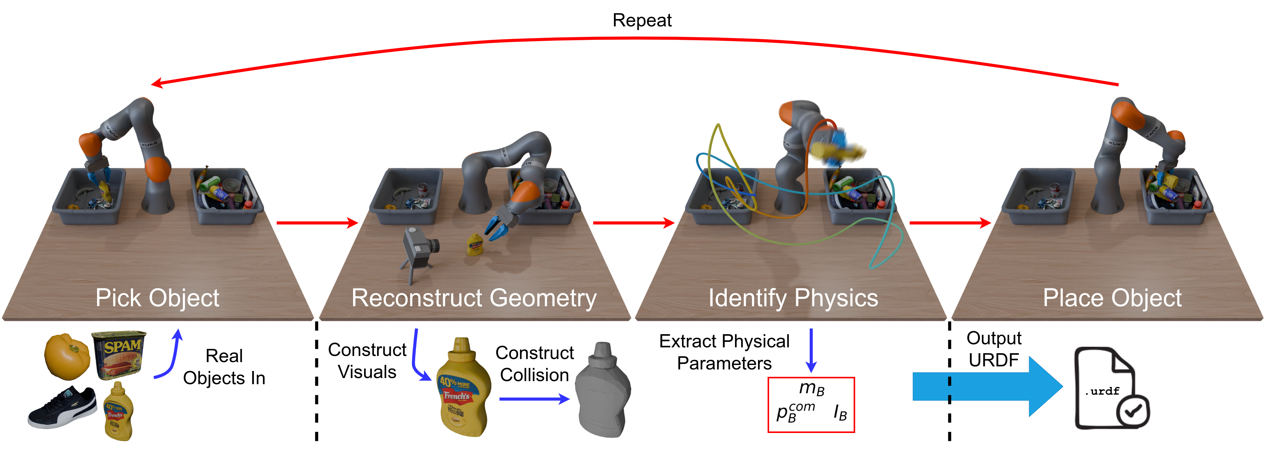
Scalable Real2Sim turns a robot's interaction with a rigid object into a simulation asset: a textured visual mesh, convex collision geometry, and estimated mass, center of mass, and rotational inertia. The robot scans objects by rotating and re-grasping them, then follows an informative motion while recording joint torques.
The reconstruction recipe separates background pixels, which should become transparent, from gripper occlusions, which should provide no training signal. The authors release an initial dataset of 20 assets and their observations. Geometry and mass estimates are promising, but rotational inertia can be inaccurate and simulated dynamics are assessed qualitatively. Contact-parameter estimation and grasp slippage remain outside the method.
I Introduction
Simulation-based learning usually depends on manually prepared geometry and tuned physical parameters. This pipeline automates both for objects passing through an existing pick-and-place setup, using a scanning camera and the robot's joint-torque sensors rather than an additional wrist force-torque sensor. It combines object-centric reconstruction, collision-mesh generation, and physically constrained inertial identification. [3] [4] [5] [6]
The demonstrated workflow deliberately scans and excites each object before depositing it in a second bin. Generating assets passively during ordinary warehouse work is a future possibility, not an evaluated capability. The released 20-object dataset supports component research without requiring a robot.
II Related Work
Prior Real2Sim systems reconstruct geometry or estimate physical parameters, often with manual handling, special hardware, or incomplete asset descriptions. Generative approaches offer scale but may invent shapes and physical properties rather than match a particular real object. Accurate parameters can matter for nonprehensile manipulation. [9] [12]
This work combines established reconstruction and system-identification tools. Its additions adapt photometric reconstruction to moving, occluded objects and provide robot-independent implementations of physical consistency constraints and informative trajectory design. Joint-torque sensing avoids a wrist sensor but measures payload forces indirectly. [17] [18] [19]
III Autonomous Asset Generation Via Robot Interaction
III-A Problem Statement
For each rigid object, the output comprises a textured visual mesh, a union of convex collision meshes, and inertial parameters. The robot picks from one bin, collects scanning views, constructs the geometries, estimates physical properties, and places the object in the other bin. The process repeats without manual intervention during the demonstrated collection run.
III-B Geometric Reconstruction for Visual Geometry
Multi-view observations are collected first; an implicit reconstruction method then produces the textured triangle mesh.
III-B 1 Data Collection and Processing
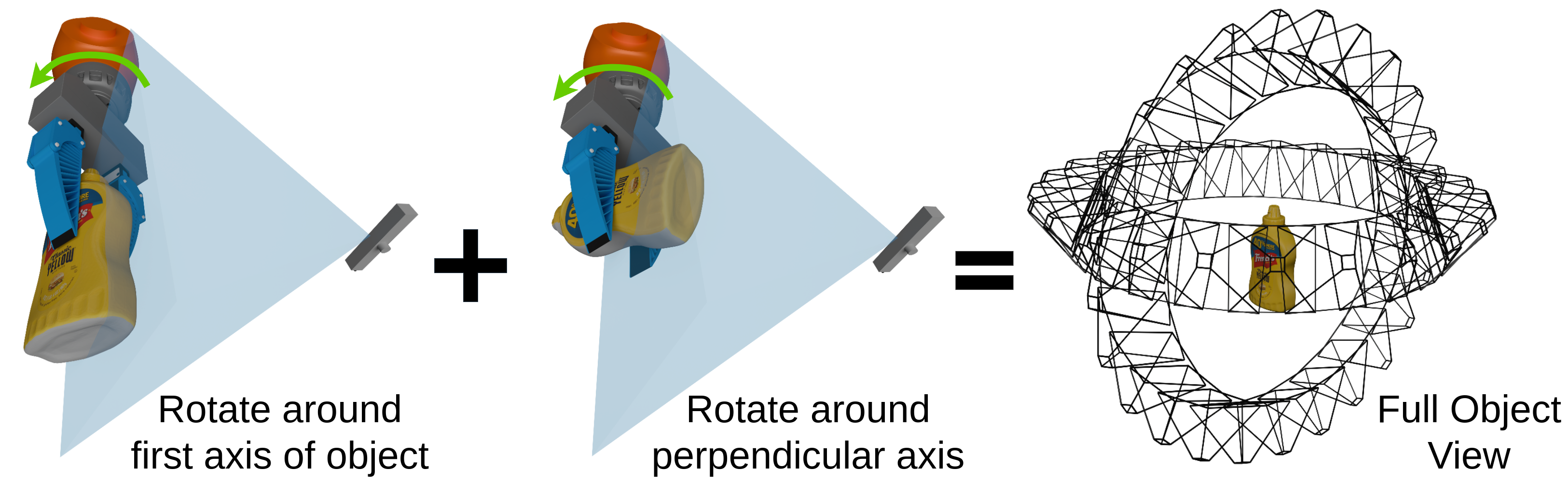
The robot presents the object along two approximately perpendicular rotation axes, re-grasping to reveal surfaces hidden by the initial grasp. Candidate grasp pairs balance antipodal quality, spatial separation, and reduced mutual occlusion. [24]
Frame selection combines regular subsampling with greedy selection of visually diverse DINO features. SAM2 tracks separate object and gripper masks through the video. Multiple views expose surfaces that a fixed grasp would leave hidden. [25] [26]
III-B 2 Geometric Reconstruction
Moving-object observations are expressed in the object's coordinate frame, so a fixed physical camera becomes a virtual moving camera around a static object. Object tracking supplies those camera poses. [27]
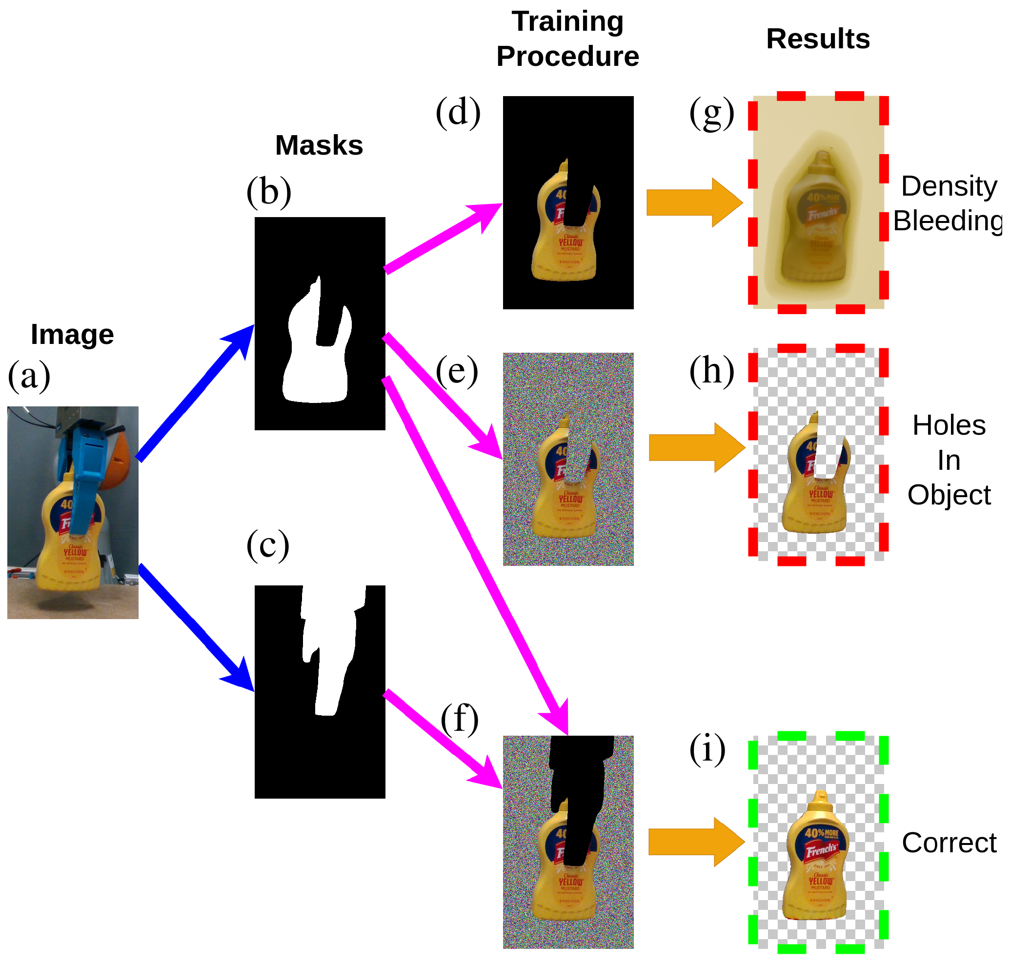
Merely excluding the background leaves empty space unconstrained and permits density bleeding. Alpha-transparent training replaces background pixels with iteration-dependent random colors and blends the same colors behind the rendered object. The model can fit those unpredictable colors by becoming transparent outside the object. [14]
Gripper-covered pixels are different: the object may exist behind them. Their loss is ignored rather than driven toward transparency, and gripper masks take precedence over object masks. This distinction prevents holes in occluded surfaces. Optional depth supervision helps photometrically ambiguous, featureless objects. The recipe applies to methods with photometric losses, including the three reconstruction approaches evaluated here.
III-C Collision Geometries
Approximate convex decomposition turns the visual mesh into simulator-friendly collision components. [28] [29] The approximation is not universally reliable: gaps can distort hydroelastic pressure fields, while overlapping components can create internal contacts in point-contact models. Primitive shapes offer another speed/accuracy tradeoff. The appropriate representation depends on the simulator and the object; a general solution remains open.
III-D Physical Parameter Identification
Identify the robot once without the payload, identify the grasped composite system, then subtract the robot contribution to recover the object parameters.
III-D 1 Parameters to Identify
The object parameters are mass, center of mass, and a symmetric rotational-inertia tensor. The first moment is mass times center of mass; the pseudo-inertia matrix combines this first moment, mass, and the second moment derived from rotational inertia. Positive definiteness enforces physical consistency. [18]
Robot identification additionally estimates every link's inertia, joint viscous and Coulomb friction, and reflected rotor inertia. Object contact parameters, such as contact friction, are not estimated and remain future work.
Equation 1
| (1) |
III-D 2 Robot Identification
The manipulator equations are affine in the lumped inertial, friction, and rotor-inertia parameters. Measured joint states and torques therefore form an overdetermined regression. Imposing physical consistency and nonnegative friction/rotor inertia makes identification a convex semidefinite program. The implementation removes unidentifiable directions and adds established regularization. [18] [19] [31]
Convexity concerns this parameter-fitting problem; it does not make the trajectory-design problem below convex or remove sensing and modeling errors.
Equations 2–4
| (2) |
| (3) |
| (4) |
III-D 3 Optimal Excitation Trajectory Design
Identification needs motion that excites the unknown parameters. The trajectory objective uses ordinary least-squares covariance as a proxy, balancing the regressor's condition number with E-optimality to reduce worst-case uncertainty. A finite Fourier series parameterizes joint motion, constrained by collision avoidance, joint limits, and zero endpoint velocities and accelerations. [21] [22] [23]
A custom augmented Lagrangian solver uses black-box optimization for its subproblems. The authors report better solutions at higher runtime than their gradient-based alternatives; this is acceptable for an offline trajectory designed once per environment. Drake's standard robot descriptions and constraint interface support reuse across robots. This is a practical optimization approach, not a guarantee of globally optimal excitation. [20] [32]
Equation 5
| (5) | ||||
III-D 4 Object Identification
Mass, first moment, and rotational inertia add linearly for composite bodies, so subtracting the unloaded final-link parameters recovers the payload estimate. Estimation error can nevertheless make the difference physically impossible. A second pseudo-inertia constraint is therefore imposed directly on the difference.
The same excitation trajectory is used for robot and object identification to mitigate systematic subtraction errors; a final-link-specific trajectory performed less well. The grasp is assumed rigid. Slippage is not modeled.
Equation 6
| (6) |
IV Implementation Details
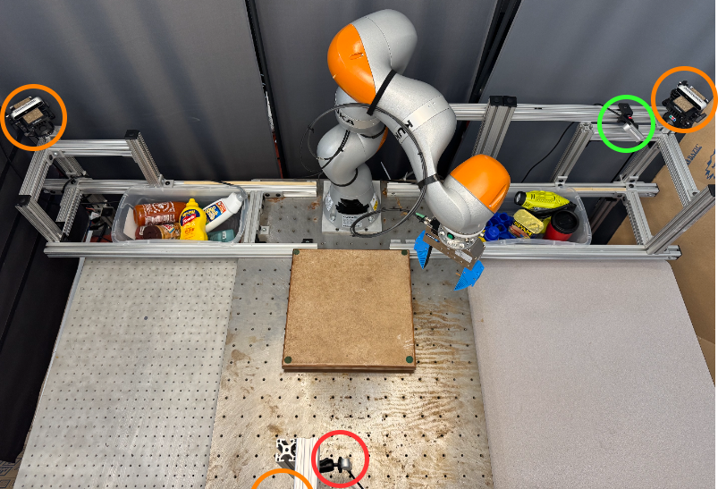
The experimental setup uses a Kuka iiwa arm, a parallel-jaw gripper with compliant fingers, and several RGBD cameras for workspace observation, bin picking, and scanning. Only one fixed camera supplies the object-scanning views. The claim of camera-based scanning does not imply that the complete demonstrated cell uses only one camera. The released code implements the pipeline.
IV- 1 Grasp and Motion Planning
Antipodal grasp detection selects grasps, and a configuration-space planning method generates collision-aware motions. [24] [33]
IV- 2 Object Tracking
BundleSDF tracks the object in the selected images using object masks, supplying the relative camera poses for reconstruction. Its own mesh is available as a byproduct and serves as one reconstruction option. [27]
IV- 3 Geometric Reconstruction
The object-centric training recipe is applied to Nerfacto, Gaussian Frosting, and Neuralangelo. [34] [35] [13]
IV- 4 Physical Parameter Identification
Robot identification averages ten repeated trajectories; each object uses one trajectory. Velocities and accelerations come from differentiating position measurements, and low-pass filtering is tuned to the identification objective. Robot calibration is repeated at several gripper openings, with the closest opening used for each object to reduce gripper-configuration error.
ICP aligns the reconstructed mesh with the point cloud and known grasp position, expressing the identified inertia in the object's frame. [36]
V Results
V-A Geometric Reconstruction
Chamfer distances to YCB scanner models are 0.93 mm for the mustard bottle, 1.68 mm for the potted-meat can, 5.58 mm for the bleach cleanser, and 0.80 mm for the gelatin box. These are four selected-object comparisons, not a dataset-wide accuracy estimate. Product changes since the original scans can also affect the distances. [39]
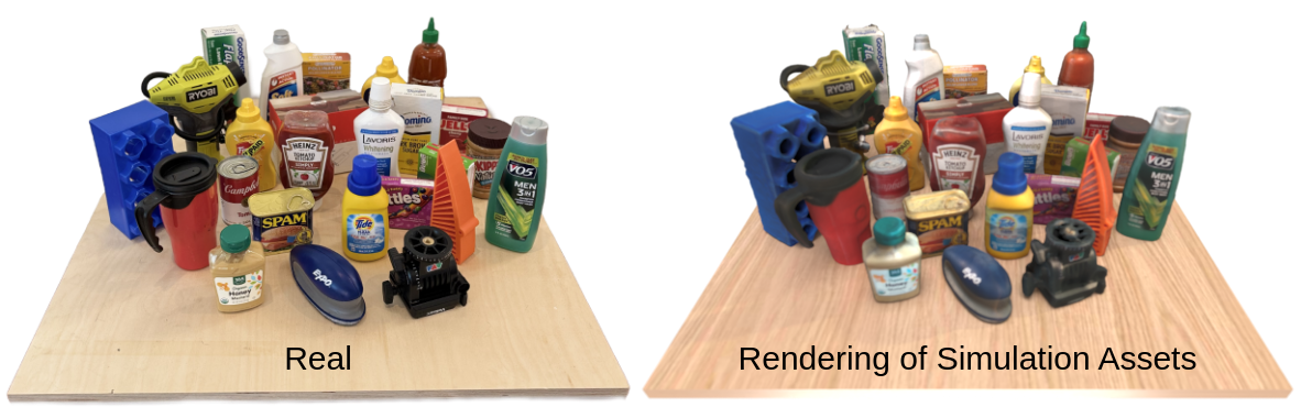
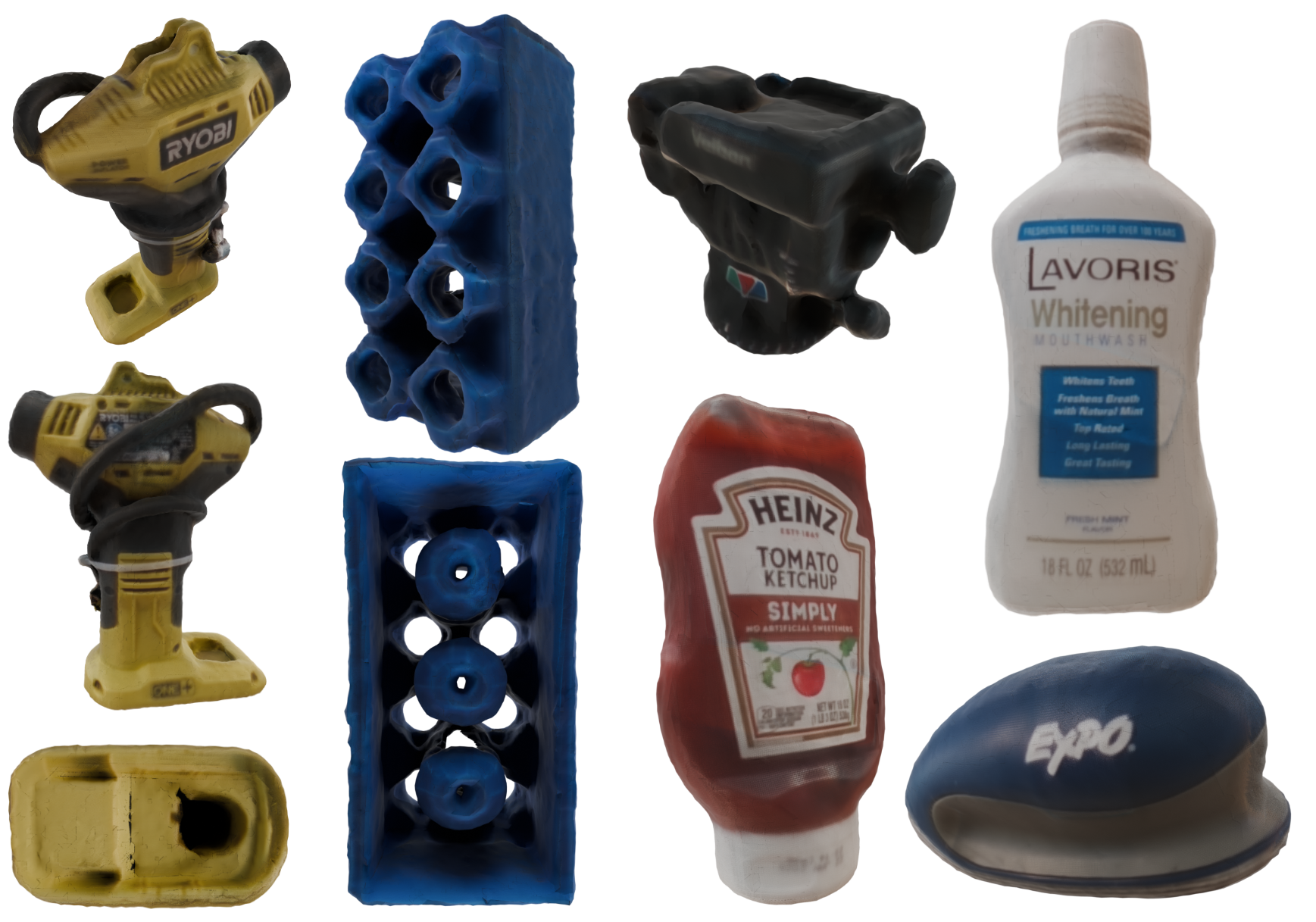
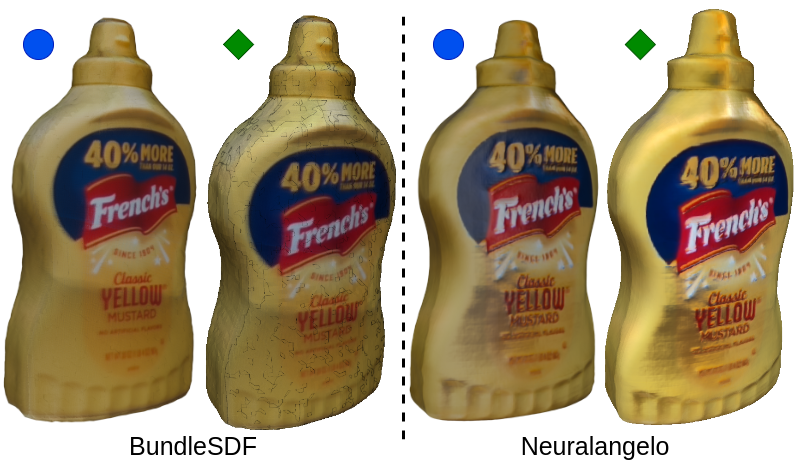
The examples show surfaces recovered through re-grasping. Figure 5's scene is manually arranged from individually reconstructed assets, rather than autonomously reconstructed as a whole. BundleSDF can produce poor mesh topology that a strong renderer partly hides; Neuralangelo produces cleaner geometry and more consistent rendering in the illustrated bottle comparison. Visual plausibility alone does not establish watertightness or reliable contact geometry.
V-B Physical Parameter Identification
The identification benchmark uses eight known-inertia configurations with three trials each, averaging 24 measurements. The test object is mounted directly to the last link. Compared with the previously reported PMD-25K force-torque-sensor results, this joint-torque method has lower mean mass and center-of-mass error but higher rotational-inertia error. Different sensing arrangements and the directly mounted benchmark should be kept in view when interpreting the comparison. [17]
In a separate end-to-end test, a 3D-printed mustard bottle has ground-truth mass 427.1 g. Errors are 1.23% in mass, 6.33% in center of mass, and 358.6% in rotational inertia under the cited benchmark metrics. Accurate mass estimates therefore do not establish accurate full dynamics; camera calibration and indirect joint-torque sensing remain material limitations. Table I's error bars are one standard deviation.
| Mass (%) | CoM (%) | Inertia Tensor (%) | |
|---|---|---|---|
| OLS (FT) | 3.18 | 24.9 | 500 |
| PMD-25K (FT) | 4.45 | 4.50 | 29.11 |
| Ours (JT) | 1.34 0.21 | 2.15 | 42.35 15.64 |
V-C Simulation Performance
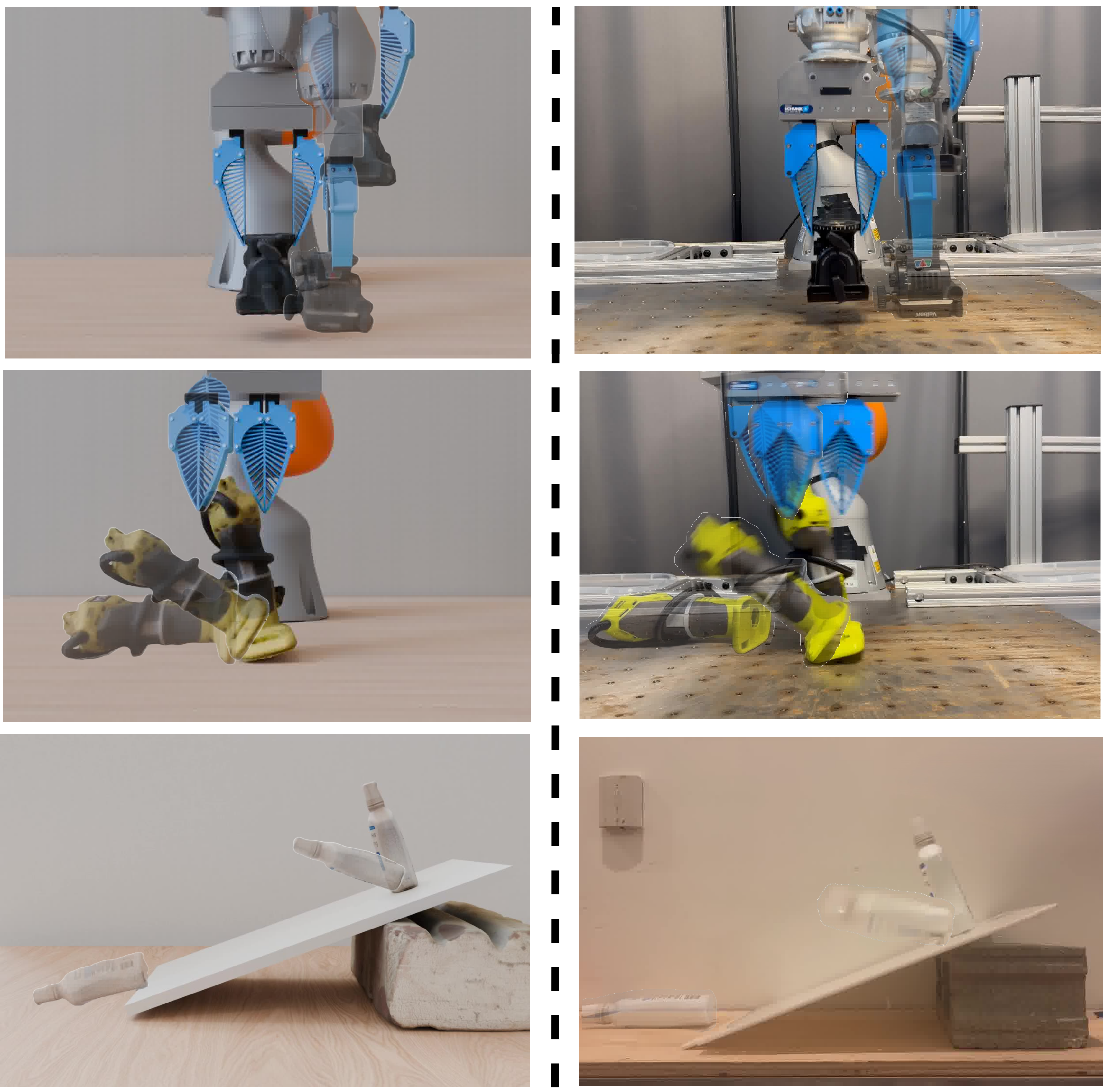
The assets run directly in a simulator, with pick-and-place, knock-over, and ramp demonstrations. These are qualitative comparisons. Individual rollouts are sensitive to initial conditions, and the study does not compare trajectory distributions or report quantitative rollout fidelity.
Resetting simulated states to measured real states could support equation-error evaluation, but sufficiently precise state estimation is outside the work's scope. Interactive simulations and demonstration videos remain on the project page.
VI Conclusion
The contribution is an integrated automated asset-generation workflow and an object-centric reconstruction recipe that handles gripper occlusion separately from background. Its demonstrated scope is rigid objects in a controlled pick-and-place cell. Scaling beyond the initial dataset still depends on robust grasping and tracking, better rotational-inertia estimates, contact-parameter identification, and stronger validation of simulated dynamics.
Acknowledgement
The work was supported by Amazon.com and the Office of Naval Research. The authors acknowledge Lirui Wang, Andy Lambert, Thomas Cohn, Ge Yang, and Ishaan Chandratreya for discussions.