At a glance
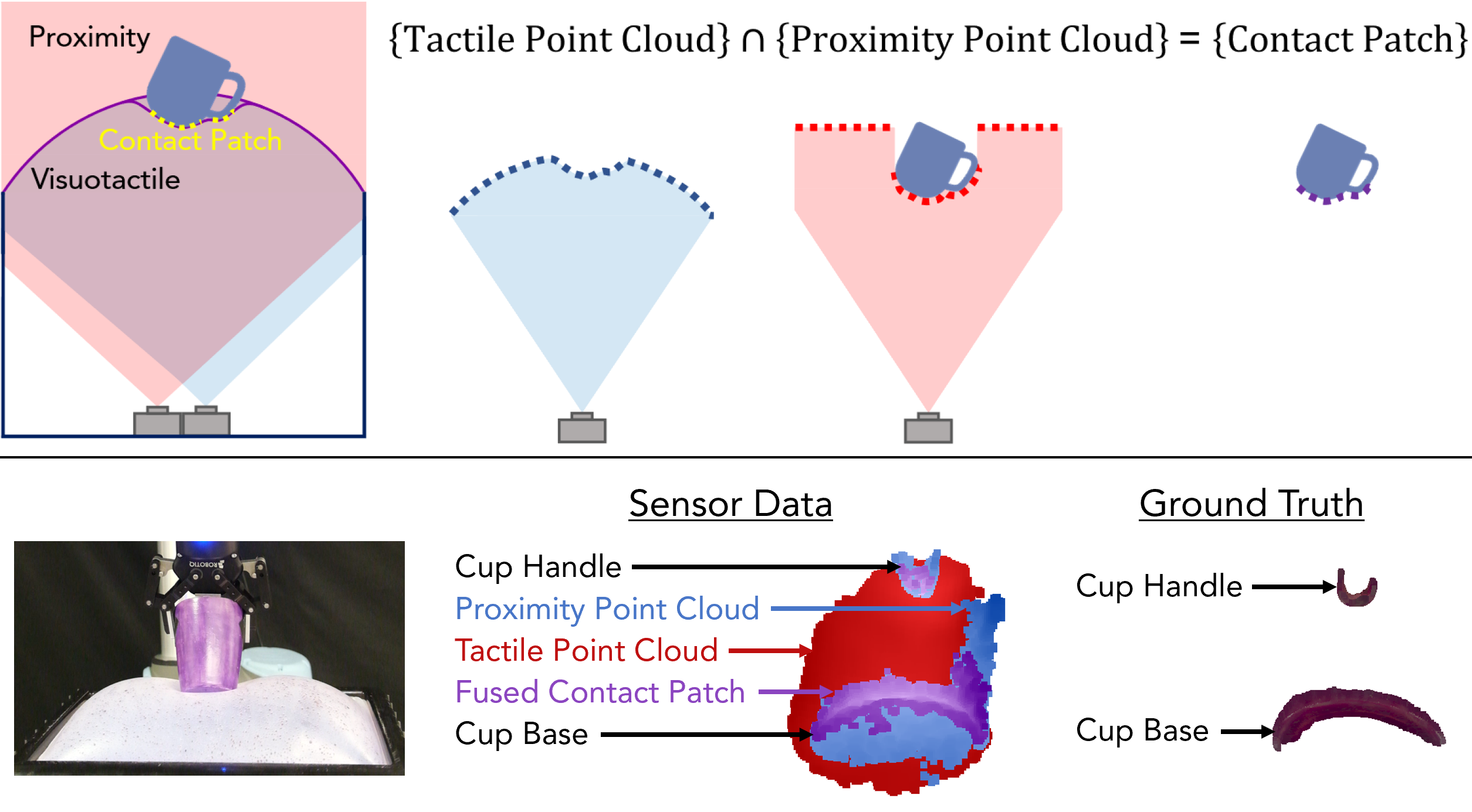
A selectively transmissive soft membrane lets one camera measure the object through infrared light while another measures the membrane through visible texture. Contact is estimated where the registered proximity and tactile depths agree within a tolerance. This avoids fitting a membrane mechanics model, allowing operation under large deformations and wrinkles.
Across three objects and three strain levels, mean contact-patch error is below 2.8 mm at each level. Additional demonstrations cover mixed-stiffness materials, wrinkling, book balancing, and known-object pose tracking. These are hardware-specific experiments with manual calibration and a tuned tolerance, rather than evidence of universal accuracy.
I Introduction
Soft sensors can conform around large objects and provide informative contact geometry. However, deformation spreads beyond the region actually touching the object, so membrane shape alone does not identify contact. Thresholds and simplified mechanics models become unreliable under large displacement, nonlinear elasticity, and wrinkles.
The proposed sensor observes both the membrane and the nearby object simultaneously. Their geometric intersection supplies a contact patch without predicting elastic deformation or contact forces. Figure 1 shows the sensing arrangement and the separated handle and base contacts of a cup.
II Related Work
Deformation thresholds require tuning for material and loading conditions. Learned contact predictors need suitable geometry, mechanics, and labeled training examples. Finite-element approaches can represent richer mechanics but require material characterization and can be expensive; linear approximations trade fidelity for speed. The method instead adds a second sensing modality that directly observes the object geometry.
III Sensor System
The device extends an earlier multimodal selectively transmissive membrane sensor [24]. An Intel RealSense L515 time-of-flight camera observes proximity through infrared transmission; an adjacent D405 stereo camera observes random dye droplets on the membrane. Their fields of view overlap across the sensing surface, and both provide 640 × 480 depth maps at 30 Hz.
The soft surface measures 355 × 205 mm and permits up to 85 mm vertical displacement from its deflated position before reaching the cameras’ minimum sensing distances. Inflation sets available compliance; proximity sensing extends about 100 mm beyond the membrane.
IV Proximity and Visuotactile Fusion for Contact Patch Estimation
The inputs are proximity RGB and depth plus tactile depth. RGB is used only to reject membrane reflections. After alignment and filtering, a depth-consistency mask selects the estimated contact patch.
IV- 1 Frame Alignment
Camera intrinsics align proximity RGB with proximity depth. A manually calibrated homography aligns tactile depth to that frame. Accurate registration is therefore a prerequisite for interpreting depth agreement as contact.
IV- 2 Proximity Pre-Processing
Curved membrane regions can reflect infrared light internally and corrupt proximity measurements. A color mask in HSV space removes pixels matching the uncontacted membrane. The mask is tuned for the lighting conditions used in the experiment.
IV- 3 Contact Patch Estimation
The retained inequality compares tactile and proximity depth at each pixel. Its relative tolerance is manually set to t = 0.03 using ground truth, corresponding to roughly 6–8 mm over the tested depths. This is a tolerance-based intersection, not exact point equality.
The mask is applied to proximity depth, which the authors find more robust to lighting changes than tactile depth. The resulting cloud undergoes statistical outlier rejection. Avoiding a mechanics model does not remove calibration, lighting, or threshold dependencies.
Equation
V Experimental Methods
Contact geometry is evaluated against thermally marked object scans. A separate strain-calibration experiment maps imposed displacement to approximate membrane strain, and three single-modality or mechanics-based algorithms provide comparisons.
| Object | Membrane Temperature (∘C) | Contact Time (s) |
|---|---|---|
| octopus | 70 | 5.5 |
| cup | 100 | 9 |
| cube | 95 | 9 |
V-A Ground Truth
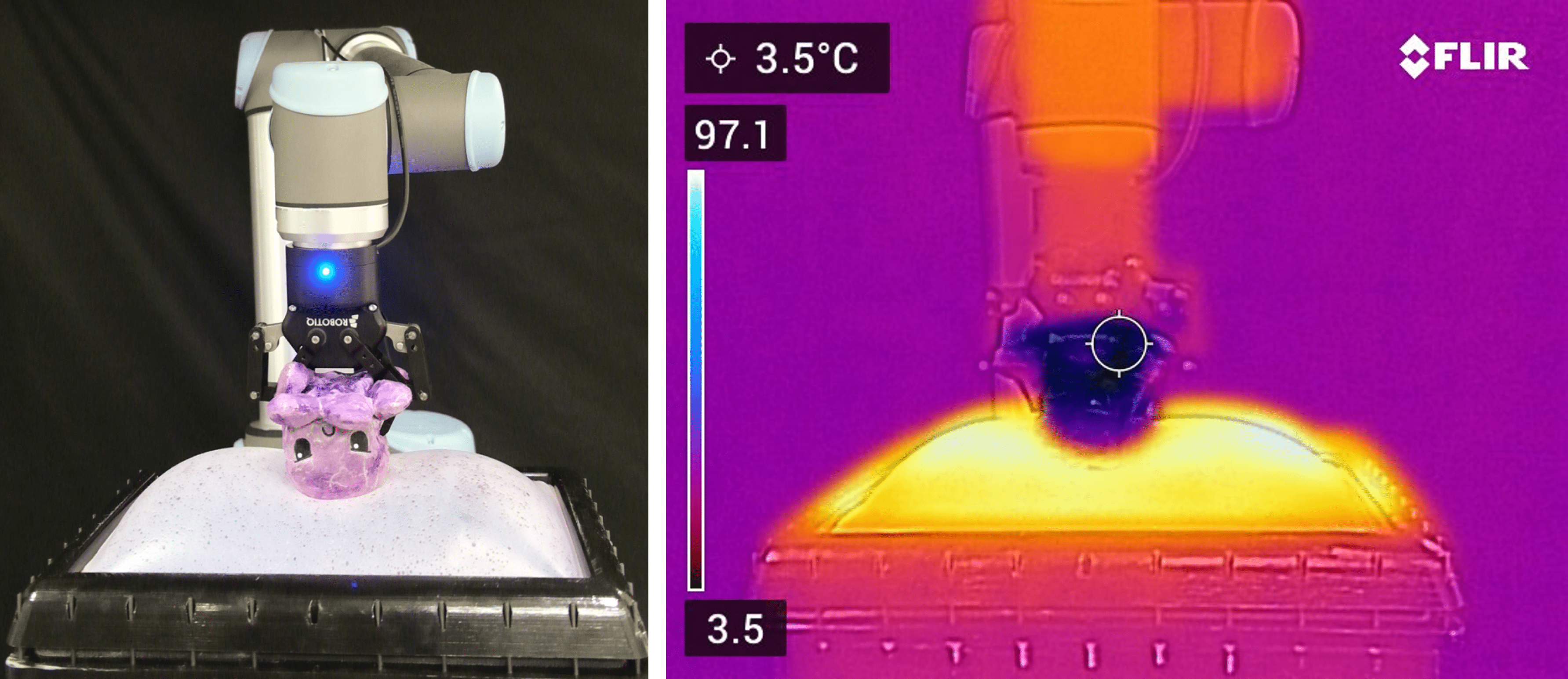
Objects receive three coats of thermochromic paint, purple when cold and pink when heated. The object is cooled to 3.5 °C; the membrane is heated to 70–100 °C. Object-specific temperatures and contact durations in Table I are chosen to avoid color change across a 1 mm noncontact gap. A thermal camera checks temperature uniformity.
After contact, an Artec Space Spider scans the object and color segmentation extracts the marked region. This measures the maximum contact accumulated during the interaction, assumed to occur at maximum deformation; it is not instantaneous ground truth for every sensor frame.
V-B Membrane Strain Measurement
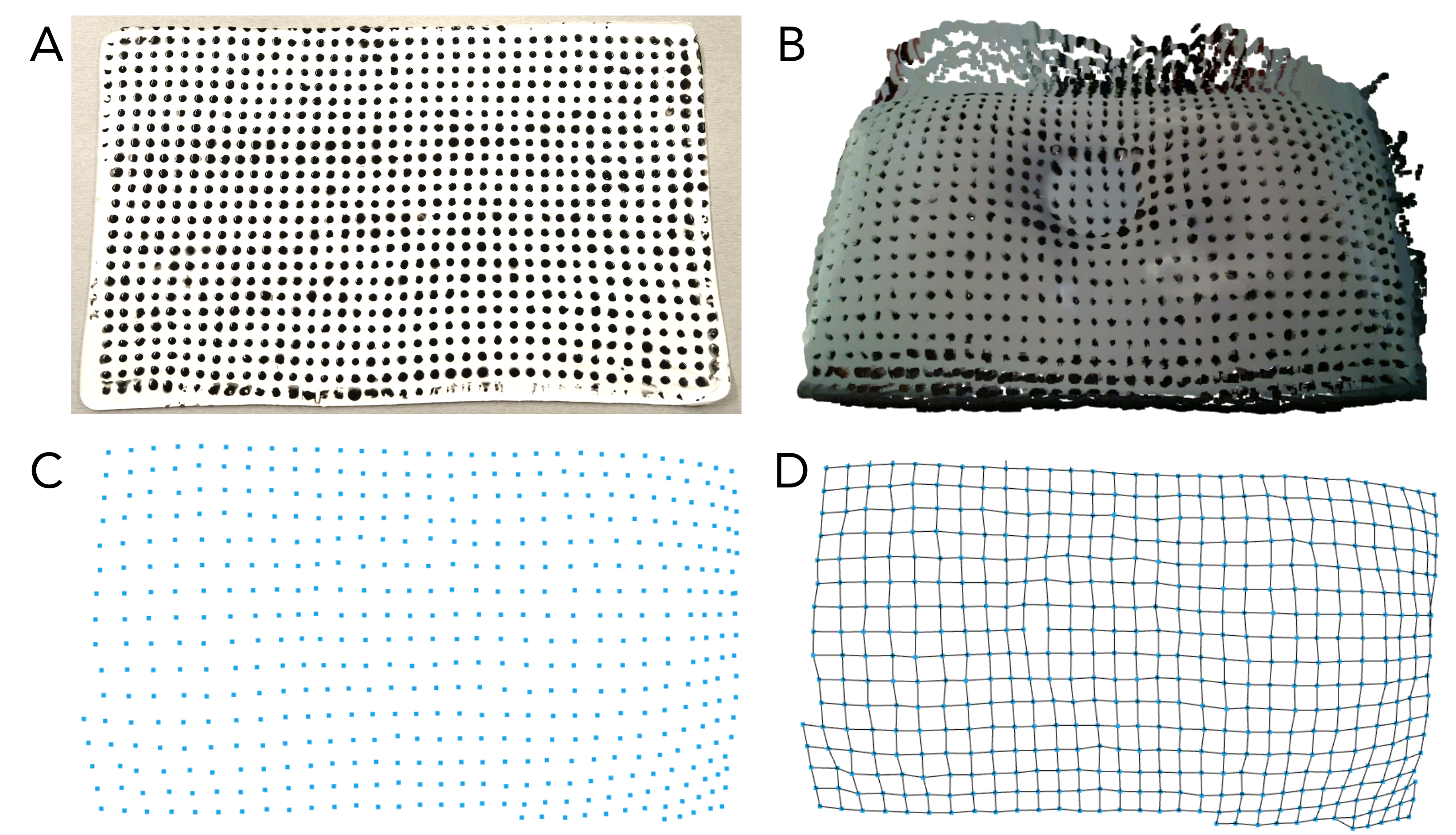
A separate opaque membrane with matching dimensions and thickness carries a 10 mm dot grid. RGB-D tracking of dot centroids estimates maximum in-plane extension along its length and width. This calibration selects displacements for nominal 10%, 60%, and 100% strain groups; strain is not reconstructed directly from the working fusion membrane.
V-C Baselines
Tactile-only and mechanics baselines use an unpatterned infrared-opaque silicone membrane with the same dimensions and L515 depth sensing. Proximity-only uses the selectively transmissive membrane. These configurations provide the inputs required by each method, so the comparison also changes membrane opacity and sensing setup.
Table II reports per-frame computation on an Intel Core i7-8650U: fusion 0.07 s, each single-modality method 0.03 s, and mechanics 0.3 s. These timings are separate from the 30 Hz camera rate and the later control demonstration on another computer.
V-C 1 Tactile-Only
The tactile baseline selects the highest 60% of deformed points relative to an inflated reference membrane. An absolute displacement threshold performed worse and is not used in the reported comparison.
V-C 2 Proximity-Only
The proximity baseline selects points closer to the camera than the inflated, unloaded reference membrane. It observes object geometry without independently checking whether the membrane touches those points.
V-C 3 Membrane Mechanics Model
The first-principles membrane model [23] estimates contact using tactile depth and internal pressure through a sparse convex quadratic program. Its assumptions include linear deformation, frictionless contact, and no wrinkling or folding. Mesh resolution also limits recovered detail.
| Algorithm | Computation Time (s) |
|---|---|
| Fusion (Ours) | 0.07 |
| Proximity-Only | 0.03 |
| Tactile-Only | 0.03 |
| Mechanics Model | 0.3 |
VI Evaluation
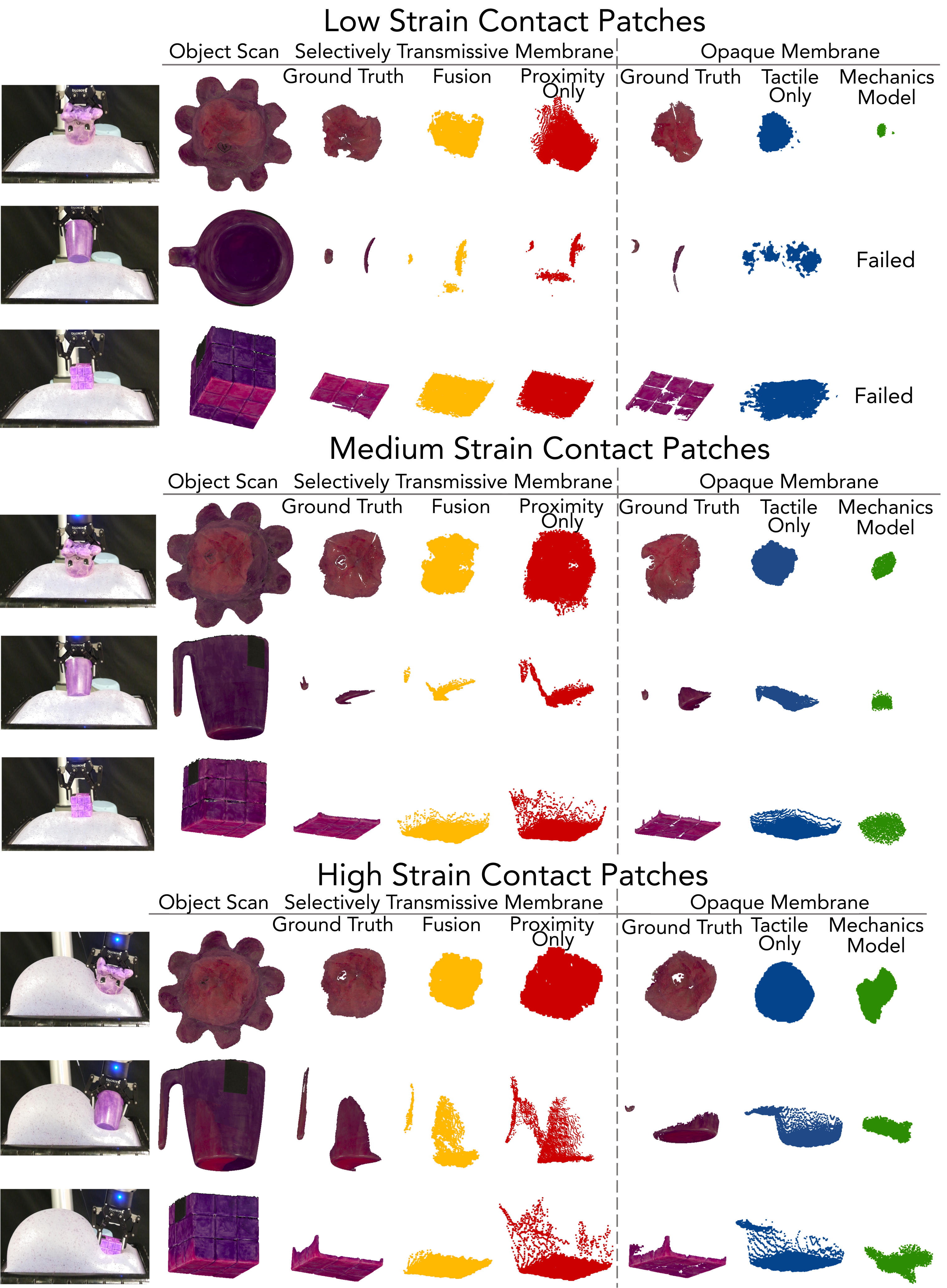
The main comparison contains nine object–strain combinations. Results are geometric errors after aligning the estimated and ground-truth contact clouds, rather than end-to-end manipulation success rates.
VI-A Experiment Setup
A UR10 arm with a Robotiq gripper presses a stuffed octopus, cup, or Rubik’s cube into the sensor. Imposed displacements are 4, 24, and 120 mm for low, medium, and high strain. High-strain trials press off-center so uncontacted membrane can expand outward.
The metric is average symmetric point-cloud RMSE after manual alignment. For the mechanics baseline, outer-edge estimates are cropped because the model produces spurious contacts while failing to predict membrane bulging. These evaluation choices matter when interpreting the numerical comparison.
| Low Strain (approx. 10%) | Contact Patch RMSE (mm) | ||
|---|---|---|---|
| Algorithm | octopus | cup | cube |
| Fusion | 1.79 | 4.96 | 1.34 |
| Proximity-Only | 2.51 | 7.41 | 1.27 |
| Tactile-Only | 3.96 | 6.74 | 1.58 |
| Mechanics Model | 13.73 | Fail | Fail |
| Medium Strain (approx. 60%) | Contact Patch RMSE (mm) | ||
| Algorithm | octopus | cup | cube |
| Fusion | 2.64 | 3.1 | 1.25 |
| Proximity-Only | 4.21 | 8.35 | 3.43 |
| Tactile-Only | 4.32 | 6.07 | 1.75 |
| Mechanics Model | 9.95 | 10.38 | 6.96 |
| High Strain (approx. 100%) | Contact Patch RMSE (mm) | ||
| Algorithm | octopus | cup | cube |
| Fusion | 3.93 | 2.85 | 1.57 |
| Proximity-Only | 2.08 | 6.63 | 4.28 |
| Tactile-Only | 4.1 | 4.2 | 3.79 |
| Mechanics Model | 8.31 | 5.9 | 8.86 |
| Overall Average for Strain Range | Contact Patch RMSE (mm) | ||
| Algorithm | low | medium | high |
| Fusion | 2.7 | 2.33 | 2.78 |
| Proximity-Only | 3.73 | 5.33 | 4.33 |
| Tactile-Only | 4.09 | 4.05 | 4.03 |
| Mechanics Model | 13.73 | 9.1 | 7.69 |
VI-B Results and Analysis
Fusion has the lowest error in seven of nine individual cases and the best reported mean at each strain level: 2.70, 2.33, and 2.78 mm. Proximity-only is better for the low-strain cube and high-strain octopus. The proposed method distinguishes the cup’s separate handle and base contacts at medium and high strain, where the compared methods struggle.
The mechanics baseline fails on two low-strain objects; its low-strain mean therefore describes only the remaining successful case. Figure 4 and Table III retain all individual results. The evidence supports these three objects and experimental configurations; it does not establish accuracy across arbitrary materials, lighting, or object geometries.
VII Demonstrations
Four demonstrations probe behaviors beyond the main object–strain comparison. They show feasibility under selected conditions, with quantitative geometry checks for two cases and qualitative control and pose examples.
VII-A Complex Membrane Mechanics
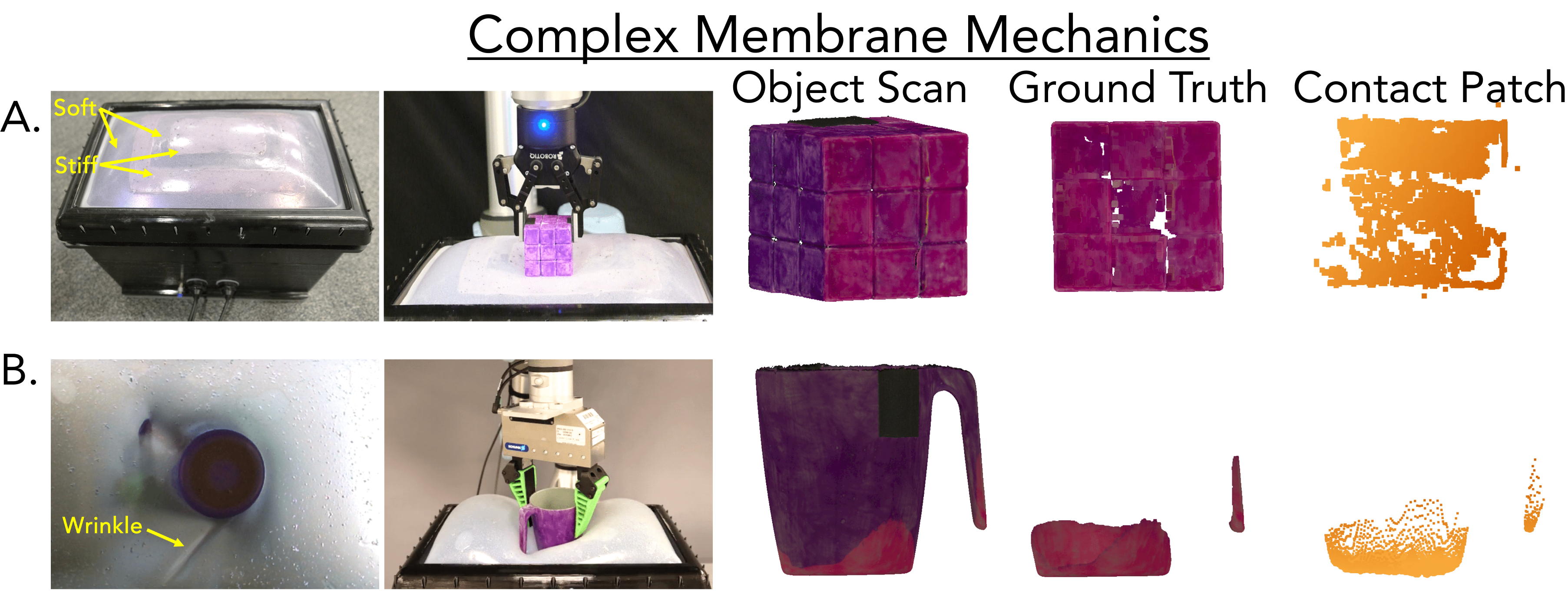
Figure 5 tests the method when material stiffness varies spatially and when applied torque produces wrinkles. Both conditions violate important assumptions of the linear mechanics baseline.
VII-A 1 Varied Stiffness Membranes
A membrane combines Dragon Skin 10 Fast and Ecoflex 00-35 Fast regions, co-cured into one surface with different stiffnesses. The medium-strain cube example yields 1.09 mm RMSE. This is one mixed-material demonstration; single-modality reference shapes or mechanics meshes would need retuning for the changed membrane.
VII-A 2 Torque and Shear-Induced Wrinkling
After pressing a cup into the membrane, the robot rotates it by 45°, creating wrinkles behind the cup and beside its handle. Fusion recovers a contact patch with 3.49 mm RMSE and captures the contacted handle geometry. The experiment illustrates tolerance of shear-induced wrinkles without explicitly modeling their mechanics.
VII-B Closed-Loop Control for Whole-Body Manipulation
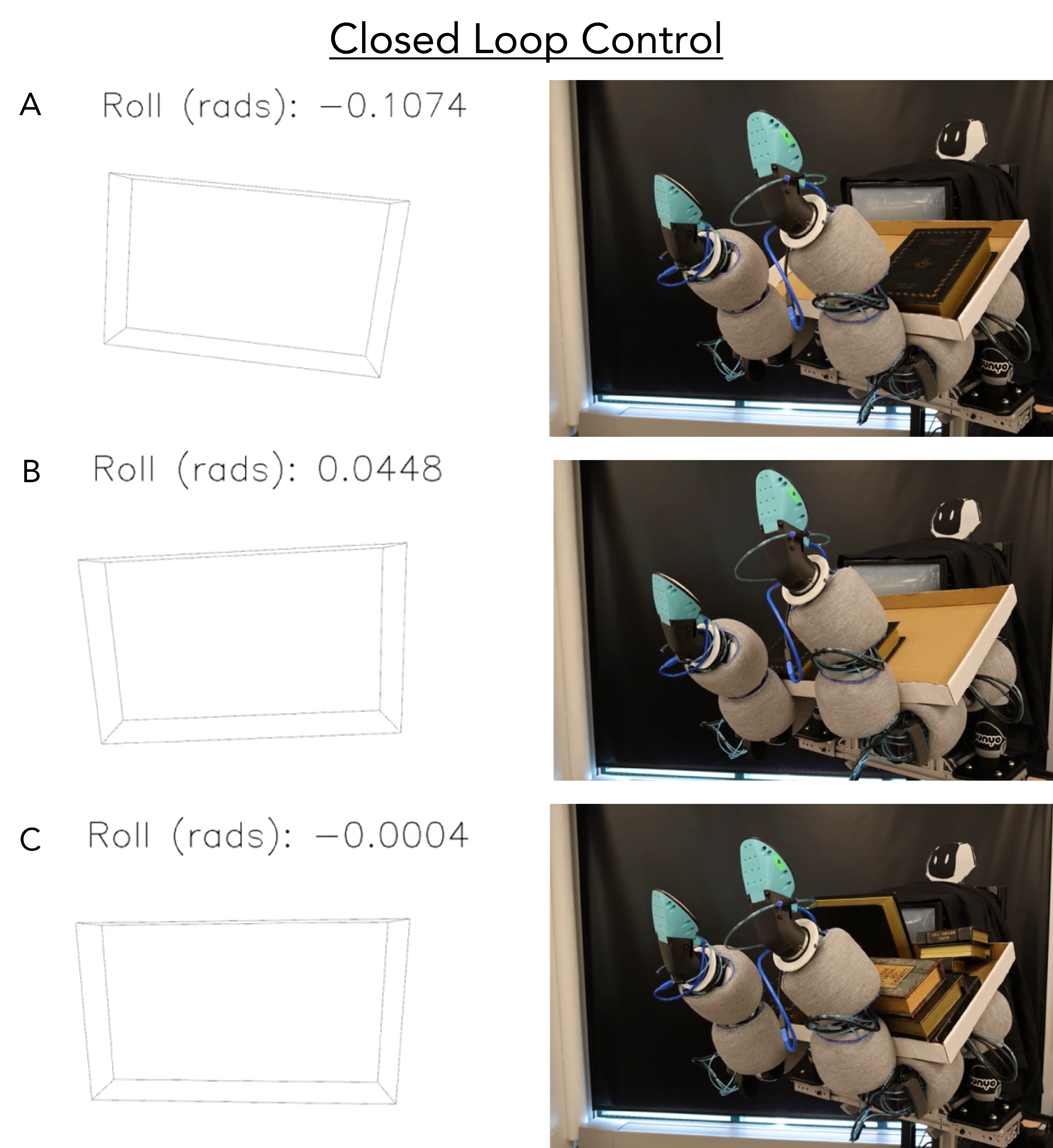
The Punyo-1 robot [31] presses a cardboard tray against its sensorized torso while two Kinova Jaco arms support it. Principal-component analysis of the contact cloud estimates tray roll as books are added. Contact segmentation avoids some proximity-only noise from the books.
A whole-body proportional–derivative controller selects two arm motion primitives to balance the load. The demonstration reports 29 Hz control using a Puget computer with 30 fps sensing. This rate should not be conflated with the 70 ms fusion timing on the separate laptop CPU.
VII-C Pose Estimation
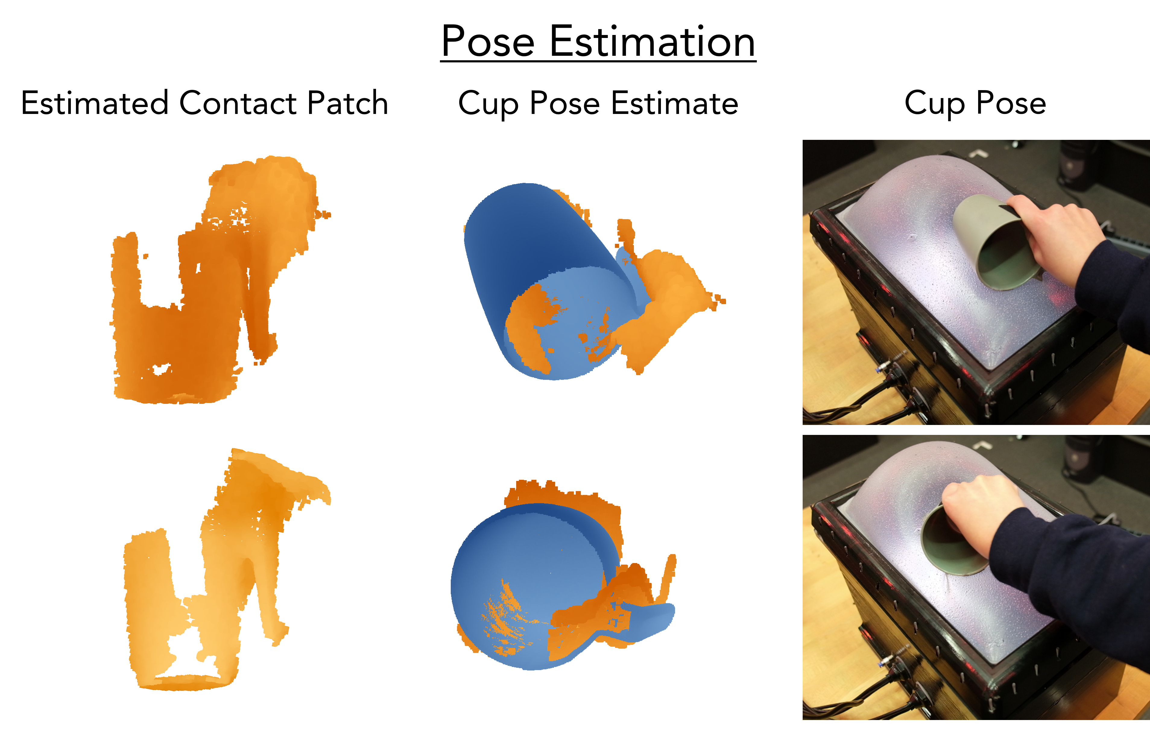
For a known cup model, the first contact cloud is manually registered and subsequent frames update the pose using Open3D’s iterative closest-point implementation [32]. A five-second sequence combines rotation about the handle with translation over the membrane.
Figure 7 shows qualitative agreement, without a numerical pose-error benchmark. Tracking becomes unstable when the handle is not observable, and adverse lighting introduces proximity noise from the hand. Joint object reconstruction and pose estimation are proposed future applications, not demonstrated capabilities here.
VIII Conclusion and Future Work
The contribution is geometric contact segmentation from two complementary depth measurements. It remains usable in selected high-strain, variable-stiffness, and wrinkled examples because it does not infer contact through an elastic model. Its practical dependencies include camera registration, membrane color filtering, and tolerance selection.
Future directions include a fingertip-scale version using shorter-range cameras and active membranes that change shape or stiffness. Neither force estimation nor general object reconstruction is established by the present experiments.
Acknowledgment
The authors acknowledge Toyota Research Institute’s PrOps team and colleagues at Penn’s GRASP Lab for hardware, experiments, facilities, and discussion.