At a glance
IKEA-Manual pairs 102 furniture models with their human-designed assembly manuals. Annotations connect realistic assembly parts, stepwise assembly trees, manual-image segmentation, and 2D–3D correspondences. Four benchmarks test plan generation, part-conditioned segmentation, part rotation estimation, and final part assembly.
The main result is a resource and a set of difficult baselines, rather than a complete autonomous assembly system. Existing models struggle with realistic parts and diagram images. Connectors and motion trajectories are excluded, and the small dataset is dominated by chairs.
1 Introduction
Visual assembly manuals break a long task into steps that communicate which parts to connect and their relative poses. Many existing shape-assembly datasets instead use synthetic semantic parts without matching manuals. IKEA-Manual joins realistic part geometry with professionally designed instructions.
The authors collect matching models and manuals, manually decompose each model into its actual assembly parts, annotate connections and diagram regions, then align 3D parts to 2D drawings using keypoints. Figure 1 shows the resulting hierarchy. Table 1 compares its annotations with related shape and IKEA datasets.
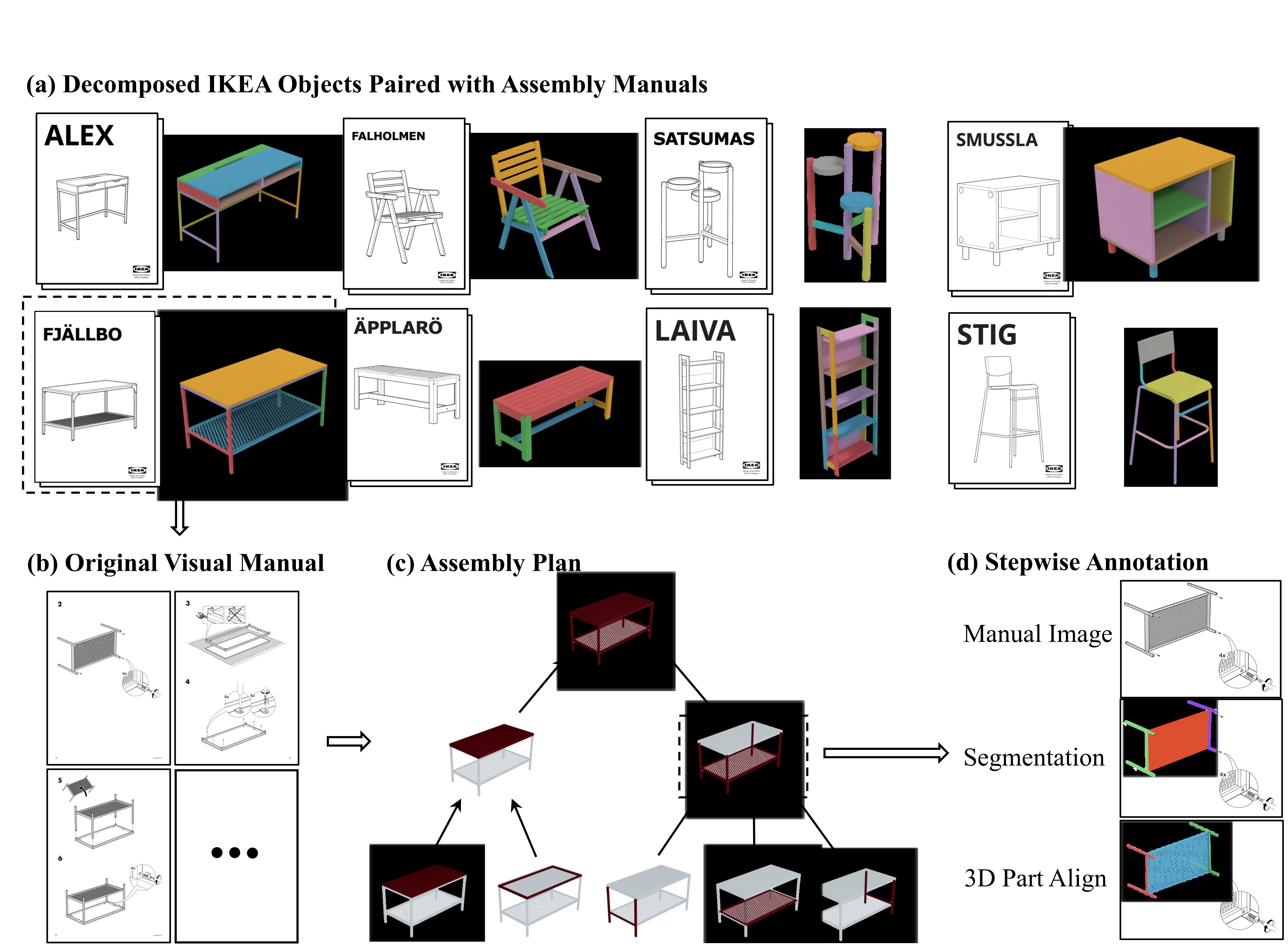
| Annotation Type | PartNet [9] | Pix3D [11] | Fusion 360 Gallery [5] | AutoMate [12] | IKEA Furniture [6] | IKEA OS [13] | IKEA-Manual | |
| Shape | Part Decomposition | ✓ | ✗ | ✓ | ✓ | ✓ | ✓ | ✓ |
| Real-World-Aligned Parts | ✗ | ✗ | ✓ | ✓ | ✗ | ✓ | ✓ | |
| Manual | Paired Assembly Manual | ✗ | ✗ | ✗ | ✗ | ✗ | ✓ | ✓ |
| Assembly Plan | ✗ | ✗ | ✗ | ✗ | ✗ | ✗ | ✓ | |
| Manual Segmentation | ✗ | ✗ | ✗ | ✗ | ✗ | ✗ | ✓ | |
| 2D-3D Correspondence | ✗ | ✓ | ✗ | ✗ | ✗ | ✗ | ✓ | |
2 Related Work
Semantic part datasets, parametric CAD models, and mechanical-joint datasets capture different aspects of structure. Their hierarchies need not represent an assembly process, and their parts often lack corresponding visual instructions. Earlier IKEA datasets provide photos, simulation geometry, or a small number of manual-paired objects; IKEA-Manual adds stepwise and dense visual annotations for 102 objects.
Shape assembly.
Pose-prediction methods assemble a final shape without necessarily planning how parts move and mate. Simulation-based construction agents address action sequences but often simplify geometry or use engineered rewards. Manual-derived plans can supply intermediate structure, although this dataset itself does not demonstrate a complete robotic controller.
Parsing human-designed diagrams.
Parsing engineering drawings, maps, and sewing patterns illustrates the value of structured diagram understanding. Earlier automatic furniture-manual parsing required specialized labeling and geometric constraints. This work uses manual annotation tools to cover a broader set of furniture.
3 IKEA-Manual
The dataset links furniture geometry, assembly steps, and the visual representation of each step.
3.1 IKEA Shape Assembly Guided by Manuals
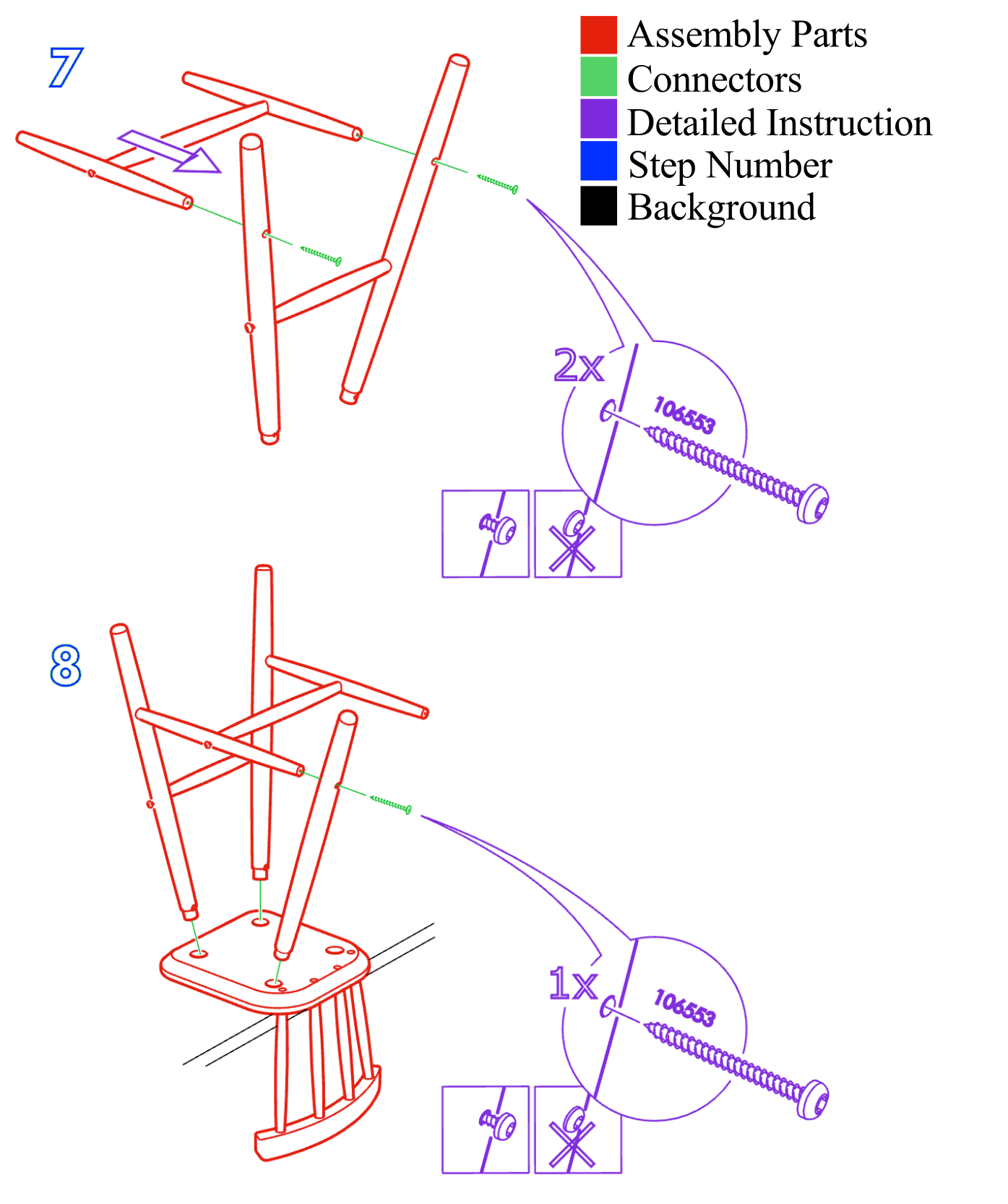
Primitive parts are progressively connected into compositional parts until the object is complete. Manual projections show which parts participate and their relative placement. Screws, hinges, other connectors, arrows, and detailed instructions are treated as background. Consequently, the annotations describe part connections and poses without modeling all physical assembly requirements.
3.2 Data Collection
Manuals come from IKEA’s website; matching models come from earlier IKEA/Pix3D/Object State datasets, 3D Warehouse, and Polantis. Objects without a sufficiently accurate matching model are excluded. This availability filter yields 102 pairs and influences the category distribution.
3.3 Annotation Types
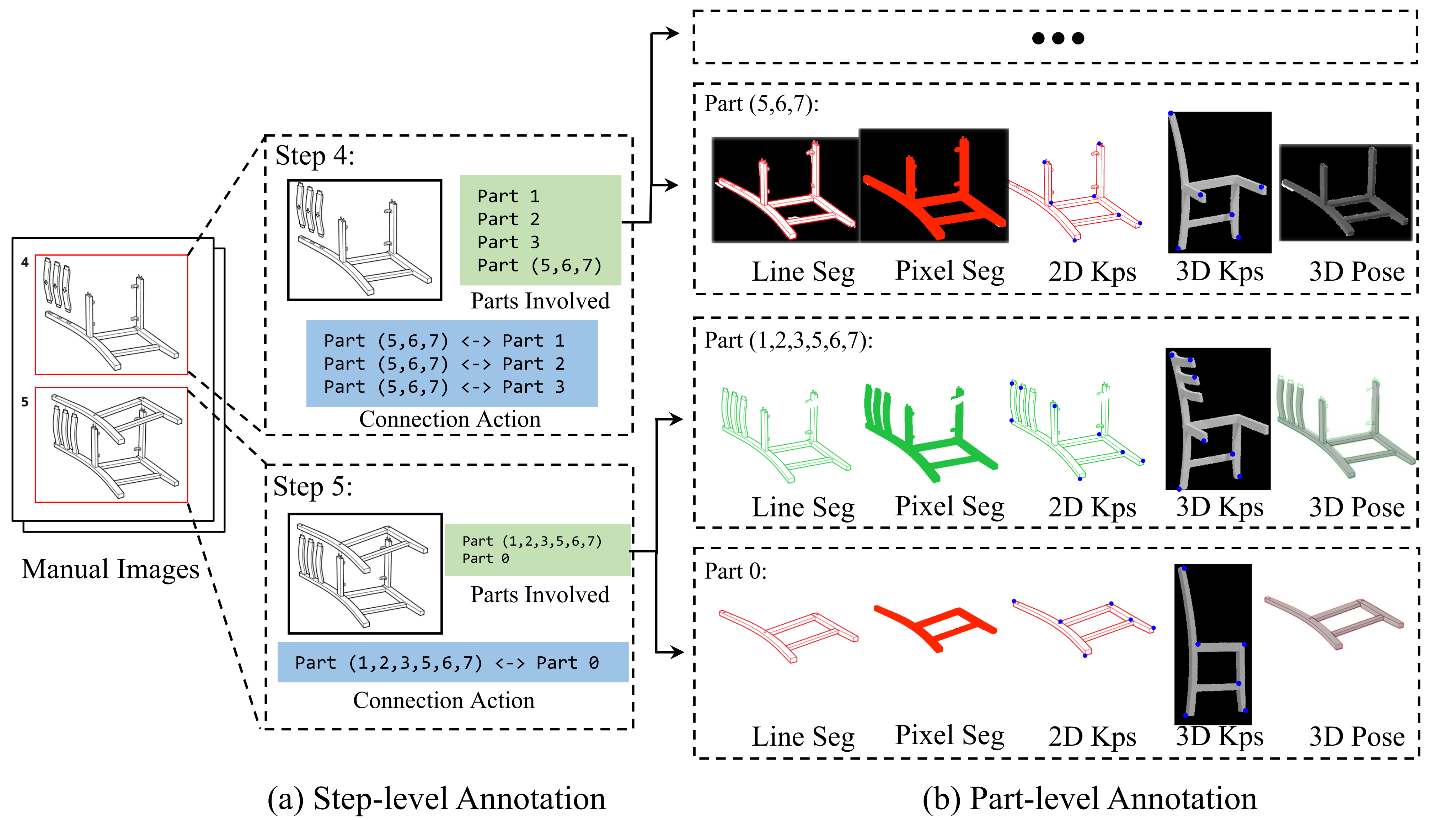
Figure 3 retains the annotation workflow from identifying a step through connections, segmentation, keypoints, and pose alignment. The following annotations describe complementary aspects of the same assembly.
Assembly part decomposition.
Meshes are manually separated into primitive parts according to the manual. These manufacturing and assembly units can span several semantic regions, such as a chair’s back and legs, so they differ from conventional semantic part labels.
Part connection relation.
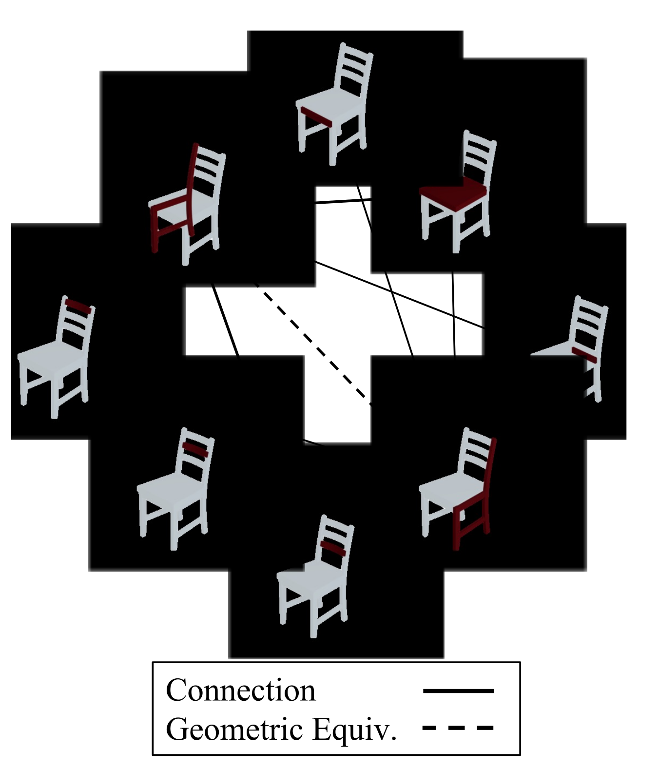
The annotations record which primitive parts directly connect in the completed object. These relations support reasoning about valid intermediate assemblies.
Part geometrical equivalence relation.
A second relation identifies parts with equivalent geometry regardless of pose. It addresses ambiguities introduced by symmetric or repeated components. Figure 4 shows both connection and equivalence relations. Manual steps that involve only connectors are excluded from the annotated sequence.
High-level assembly plan.
Each internal node of the assembly tree represents an intermediate assembly; its children are the parts combined in that step. Leaves represent primitive parts. The tree supplies high-level planning structure and a target for plan generation, while omitting detailed connection motions.
Visual manual segmentation.
Vector primitives in each diagram are assigned to a part or background, giving line-level instance segmentation. Additional pixel masks include each part’s interior. These two representations support sketch-based and pixel-based manual interpretation.
2D-3D alignment between parts and manuals.
Annotators mark corresponding keypoints on each 3D part and its 2D diagram projection. Efficient Perspective-n-Point (EPnP) estimates the pose. The supplement details focal-length search and iterative quality checks; these are manually supported alignments rather than automatically obtained ground truth.
3.4 Dataset Analysis
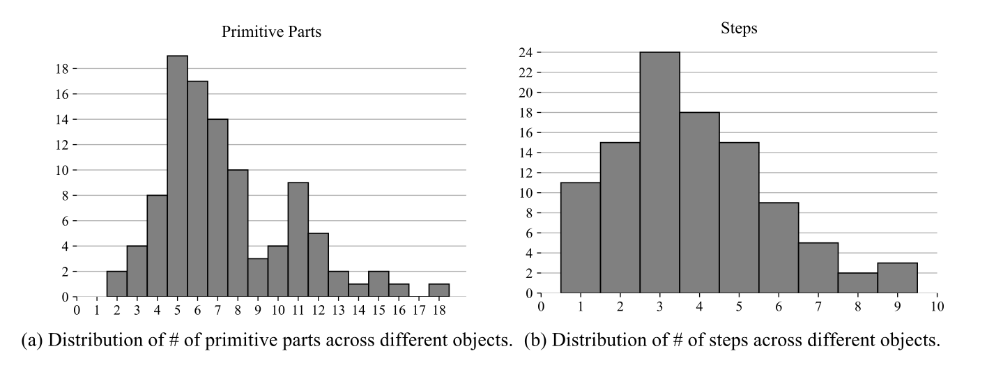
The dataset reports 102 objects, 393 steps, and 1,056 annotated part masks and poses. Figures 5 and 6 preserve the distributions and examples. The text lists 57 chairs, 19 tables, eight benches, four desks, three shelves, and eight other objects; these category counts sum to 99, so they do not account consistently for the stated total of 102.
Chairs dominate because suitable models are more available online. Real assembly parts frequently combine regions assigned separate semantic labels in other datasets, which creates a meaningful transfer challenge.

4 Application
Four experiments probe the resource at different levels: assembly-tree prediction, part segmentation in manuals, rotation estimation, and final arrangement of parts.
4.1 Assembly Plan Generation
Assembly-tree generation predicts a hierarchy from a target shape’s parts. Evaluation compares the generated tree with the professional manual’s tree. This offers an automatic structural metric, but it does not directly measure clarity, physical feasibility, or whether an alternative valid plan is preferable.
Assembly tree representation.
A node corresponds to a nonempty subset of primitive parts, the root contains all parts, and each internal node’s children partition its subset. The original formal constraints are retained below. A postorder traversal supplies an order consistent with the hierarchy.
This representation omits the motions used to connect parts and how those actions appear in the manual. Predicting a tree is therefore a precursor to generating complete illustrated instructions.
Equations
Problem formulation.
Each primitive part is supplied as a 3D point cloud. The model must produce a valid tree over these parts; the retained notation specifies the point-cloud dimensions and part index range.
Equation
Metrics.
Simple matching pairs internal nodes containing the same primitive-part set. Hard matching additionally requires their children to match under the simple criterion. Precision and recall use matched, predicted, and reference internal-node counts; the original formulas are retained. These criteria compare intermediate assemblies and grouping actions, not motion order or feasibility.
Equation
Baselines.
SingleStep connects every primitive part directly to one root. GeoCluster extracts pretrained DGCNN features and recursively groups geometrically similar parts. The complete clustering algorithm and hyperparameters are restored from the separate supplement.
| Simple Matching | Hard Matching | |||||
| Prec | Rec | F1 | Prec | Rec | F1 | |
| SingleStep | ||||||
| GeoCluster | ||||||
Results.
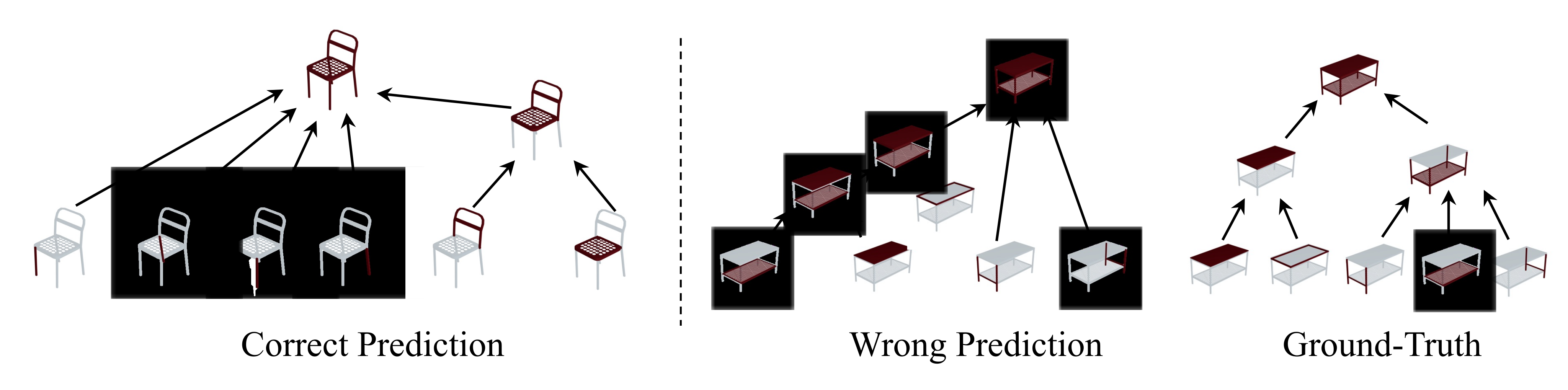
Table 2 shows that neither heuristic recovers detailed manual structure well. SingleStep attains 100% simple precision because its sole internal node—the root—is always present, but recall is only 35.77%. GeoCluster improves simple recall to 48.46% and hard F1 to 16.30%, while its simple F1 is lower than SingleStep’s. Figure 7 shows that geometric grouping alone can violate connection constraints.
4.2 Part-Conditioned Manual Segmentation
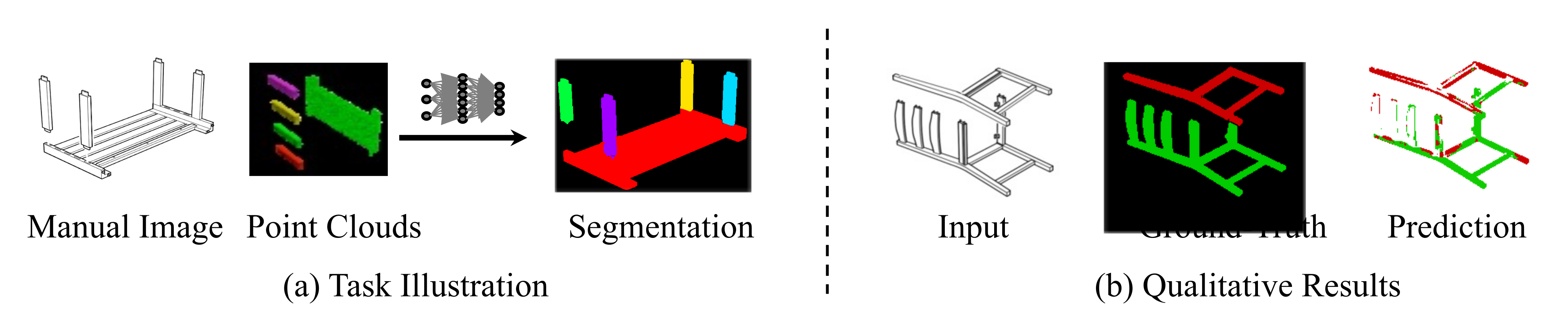
The input is a cropped manual step and point clouds of its participating parts; the output is one mask per part. A U-Net conditioned on PointNet-family geometric features is initialized from a PartNet-chair model and fine-tuned on 353 steps, with forty test steps.
The reported single-run IoU is 25.31%; three supplemental runs yield 25.58 ± 0.95% standard error. Figure 8 illustrates failures on complex compositional parts. The described step-level split does not establish generalization to entirely unseen furniture objects.
4.3 Part-Conditioned Pose Estimation
This benchmark predicts a part’s rotation from its geometry and its diagram appearance. It does not evaluate the entire assembly pose or a robot’s manipulation action.
Setup.
The 1,056 part examples are randomly split into 844 training, 105 validation, and 107 test cases. Comparisons include a random rotation, Xiao et al.’s image/point-cloud network, and SoftRas optimization. The learned baseline receives an image masked by the target part’s annotated segmentation; SoftRas also uses masks and multiple initializations. Thus the experiment assumes segmentation information rather than evaluating fully automatic manual parsing.
Metrics.
Metrics include median rotation error, accuracy below 30 degrees, Chamfer distance between rotated point clouds, and Chamfer accuracy at a 0.05 threshold. Shape-based metrics accommodate some geometric symmetries that make a unique rotation ambiguous. Table 3 retains all values and reported inference times.
| Rotation Error | Rotation Accuracy | CD | CA | Inference Time (s) | |
| Random | N/A | ||||
| Xiao et al. [44] | |||||
| SoftRas [47] |
Results.
SoftRas achieves a median rotation error of 64.81 degrees, 24.30% rotation accuracy, and 51.4% Chamfer accuracy. The learned baseline reaches 82.79 degrees, 20.56%, and 49.53%, respectively. Optimization is better but much slower; both remain far from reliable rotation recovery. The unusually small learned-model timing is retained as reported, without an independent timing audit.
4.4 Part Assembly
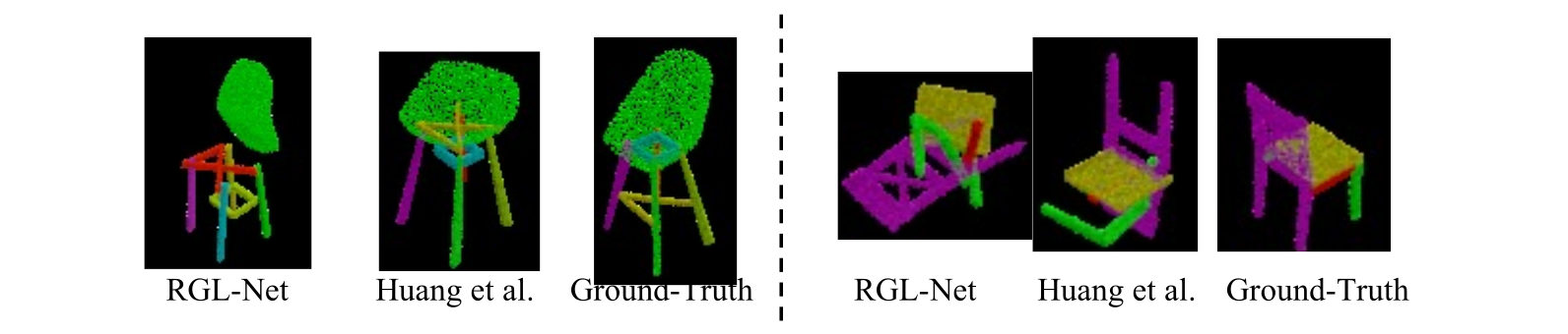
Part assembly predicts a pose for every canonical part so their union forms a plausible final object. Figure 9 preserves successful-looking and failed arrangements.
| PartNet [9] (Chair) | IKEA-Manual (Chair) | |||
| Shape CD | Part Accuracy | Shape CD | Part Accuracy | |
| B-LSTM [4] | ||||
| B-Global [4] | ||||
| RGL-Net [20] | N/A | N/A | ||
| RGL-Net [20]* | ||||
| Huang et al. [4] | ||||
Setup.
Evaluation uses IKEA-Manual chairs with checkpoints trained on PartNet chairs. Methods include graph-based refinement, recurrent graph learning, and global/LSTM baselines. Shape Chamfer distance measures the overall union; part accuracy measures the fraction of parts below a 0.01 Chamfer threshold relative to the corresponding target part.
Results.
All comparisons degrade substantially when transferred to realistic part decompositions. Huang et al.’s model has the best IKEA-Manual result in Table 4, but part accuracy falls from 39.96% on PartNet to 6.90% here. A roughly chair-shaped union can conceal badly placed individual parts, explaining why overall shape distance looks less severe than part accuracy.
5 Discussion
IKEA-Manual provides structured supervision connecting actual assembly units to human-designed diagrams. Its limitations include omitted connectors and motion details, a small availability-filtered sample, chair imbalance, and human annotation noise. The baselines demonstrate difficulty rather than a complete solution. The authors also discuss possible displacement of manual-design work and license-respecting use.
Acknowledgements.
The authors thank Stephen Tian and Hong-Xing (Koven) Yu. Support came from Autodesk, Stanford HAI and CIFE, NSF and ONR programs, and several industry sponsors.
Supplement 1 Annotation Methodology
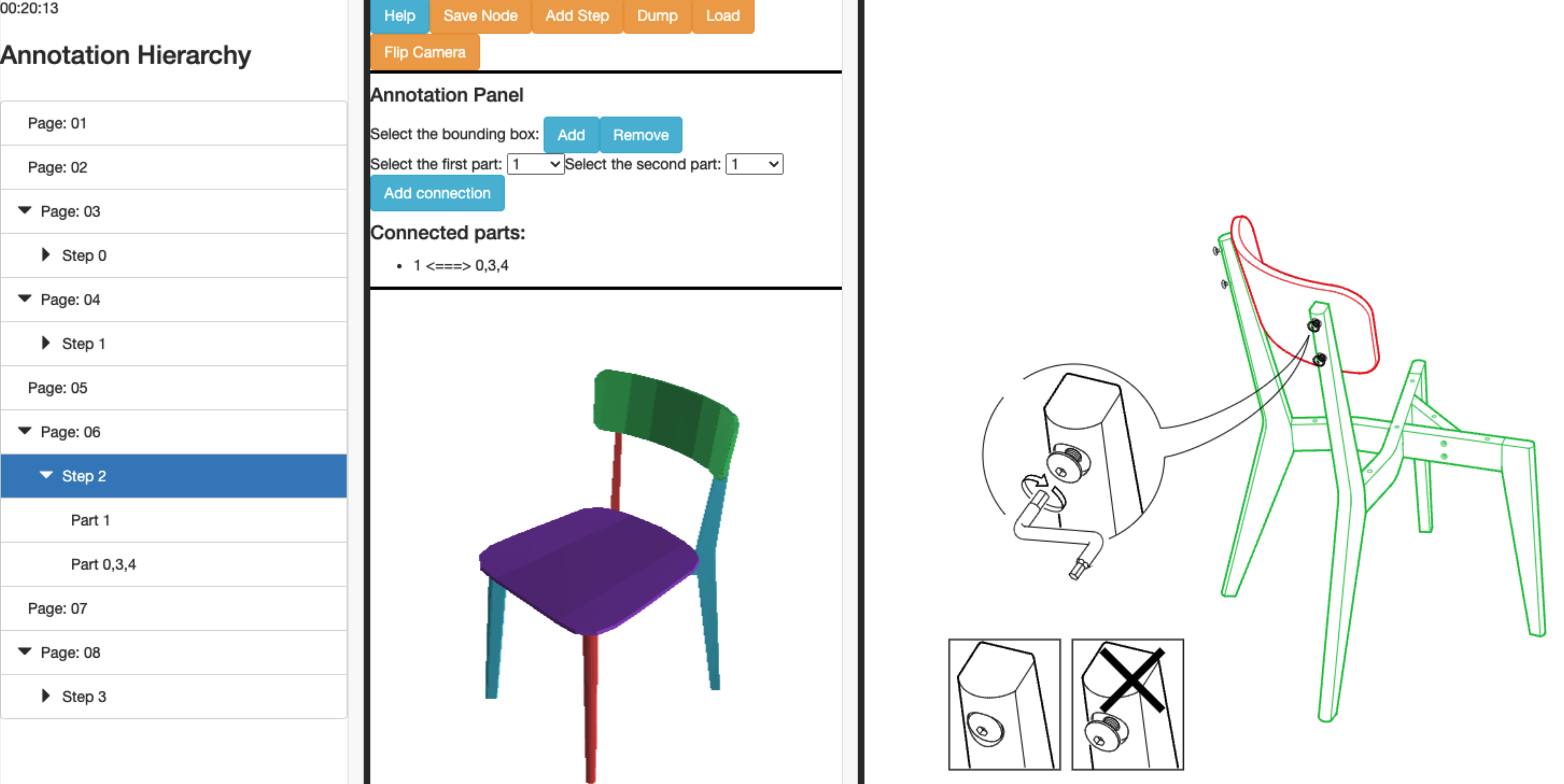
The separate official supplement describes the annotation interface and quality controls. Its Figure 1 is retained below. Two demonstration videos are available in the official supplemental archive.
1.1 Overview
Each model is centered by its axis-aligned bounding box and scaled so the box diagonal has unit length. Annotators use Blender to group mesh faces into assembly parts, repair missing or inaccurate components, and assign part identifiers.
A web interface derived from PartNet supports step selection, connection labels, vector-stroke segmentation, and paired 2D/3D keypoints. Flood filling turns line annotations into pixel masks, while EPnP renderings provide feedback for pose refinement.
1.2 Annotation Details
Connection candidates are proposed using a Chamfer-distance threshold of 5 × 10⁻⁶, then checked against the manual. Geometric-equivalence candidates use normalized meshes, 2,000 farthest-point samples, PCA alignment, and a 0.06 distance threshold before manual review. Neither proximity test alone defines the final relation.
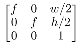
For pixel segmentation, annotators seed background regions to prevent holes and nonconvex regions from being filled incorrectly. Remaining interiors are flood-filled as parts. For alignment, the camera assumes zero skew, square pixels, and a centered principal point, with the original intrinsic matrix retained below.
Focal length is searched from 300 to 4,000 in steps of ten; EPnP estimates pose for each candidate and reprojection error chooses the result. Annotators supply five to eighteen keypoints per part and refine low-quality fits. Projected masks attain a mean 71.3% IoU against annotated masks across 1,056 poses, indicating residual alignment error.
Equation
Supplement 2 Details for Manual Plan Generation
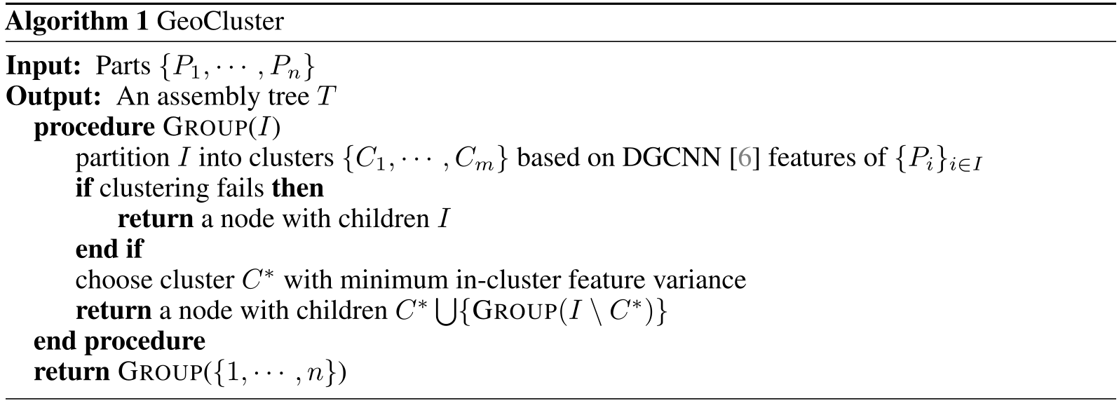
GeoCluster uses a 1,024-dimensional DGCNN feature after global max pooling, pretrained for object classification. It tries KMeans with two and three clusters and selects the result with the highest silhouette coefficient. A threshold determines failure; the chosen cluster with smallest mean pairwise feature distance is grouped first, and the procedure recurses on the remaining parts.
The threshold is the negative of the within-cluster variance computed by treating all parts as one cluster. The original complete Algorithm 1 is retained, including its base case and recursive grouping expression.
Supplement 3 Additional Experiment Results
Three segmentation runs yield mean IoU 25.58 with standard error 0.95; training takes about an hour on one Titan RTX. Supplemental Table 1 gives means and standard errors across three runs for chair part assembly. The accompanying text mistakenly calls this Section 4.3; the table corresponds to the main paper’s Section 4.4, rather than providing pose-estimation error bars.
| IKEA-Manual (Chair) | ||
|---|---|---|
| Shape CD | Part Accuracy | |
| RGL-Net [8] | 0.0583 ± 0.00002 | 2.01 ± 0.00000 |
| Huang et al. [9] | 0.0151 ± 0.00006 | 6.90 ± 0.00000 |
Supplement 4 Datasheets for Dataset
The supplement follows Datasheets for Datasets to document intended use, provenance, distribution, and maintenance. The following statements describe the release plan at publication time.
4.1 Motivation
The authors created the resource to study assembly-manual generation and interpretation. Stanford and Autodesk funded dataset creation; participating researchers were affiliated with Stanford, MIT, and Autodesk.
4.2 Composition
The hierarchy comprises 102 object instances and 393 step instances. Object data include mesh parts and JSON connection/equivalence relations; step data include assembly trees, segmentation masks, and pose matrices. Step-to-object membership is explicit.
The sample is incomplete by design, and human labeling may introduce decomposition, mask, and pose errors. Task-specific splits are supplied. Original manuals remain external resources owned by IKEA, with download links/scripts planned. The authors report no personal, confidential, or offensive data.
4.3 Collection Process
Author-list students collected and annotated the data from February to May 2022. They selected IKEA objects, searched online repositories for models, and included only cases matching the manual’s projections. This matching and availability requirement constrains the sample despite the initial selection being described as random.
4.4 Preprocessing, cleaning, and labeling
Manual preprocessing includes mesh decomposition, segmentation, and keypoint-based pose estimation. The authors planned to distribute raw data alongside labels and to release the annotation software.
4.5 Uses
The demonstrated uses are assembly-plan generation, manual segmentation, pose estimation, and part assembly; the authors also suggest 3D reconstruction. The publication-time datasheet reports no earlier third-party uses. Its broad statements about permissible tasks do not remove the practical biases and annotation limitations described in the paper.
4.6 Distribution
The publication-time plan was public distribution through Zenodo with persistent identifiers. Manual annotations are licensed CC BY-NC-SA 4.0; original manuals and 3D models retain their creators’ rights. These are distinct components with distinct ownership, as documented in the supplement.
4.7 Maintenance
The authors commit to maintaining external links, correcting annotation errors, and recording new versions on Zenodo while preserving older versions. Questions and contributions are directed to the corresponding author; the annotation license permits derivatives under its stated conditions.